
It’s near the end of January. Oil is back over $30, Bitcoin is (yet again) doomed, and I’ve just spent the last two posts detailing a teardown of a Trek Ride+ Valencia battery pack.
If you haven’t read them, you really read both to understand where this post is coming from. It’s hard to appreciate the rebuild without understanding the horrors of the teardown.
Trek Valencia Ride+ BionX Battery Pack Teardown: Part 1
Trek Valencia Ride+ BionX Battery Pack Teardown: Part 2

And now, I’m going to rebuild it. Read on, because you know you want to see what happens!
Rebuild Overview
This rebuild is going to be a little bit different from my previous ones. I’m not exactly duplicating the previous pack design, but instead using a different cell layout.
The original pack is 4P11S - sets of 4 cells wired in parallel, then 11 of these sets in series. I’m going to rebuild this pack as 11 cell series sets, and then wire the 4 of these in parallel.
There are several reasons for this. The first is that I saw what happened to the 4P11S pack with the horror show of negative voltages across many of the parallel groups. I haven’t seen this on the other BionX packs I’ve torn down (which were series then parallel), so I’m inclined to go with the layout I know works.
The second reason is that the 4P11S layout is actually very difficult to build, and rebuilding it would be incredibly tricky. Since there are 4 groups of 11 cells, doing them series then parallel makes it radically easier to build.
Finally, I reduce the resistance losses in the nickel strip significantly, since instead of the full pack current flowing through the nickel strip, only 1/4th the pack current is flowing through the strip - so losses are 1/16th (P=I^2*R). Nickel is not the most conductive material on the planet, so reducing the losses there should help with the range.
These combined to make it, in my opinion, worth rebuilding the pack differently.
I keep the chemistry the same, using 2250mAh Sony US18650V3 cells to replace the 1600mAh Sony US18650V cells. This means a 9Ah pack instead of a 6.4Ah pack, though!
Function Check
This pack is a newer CANBus pack. I’ve heard about problems with them not working after a rebuild, so I set out to find out as much as I can about testing them first. I obviously can’t just stick it on a bike to test, since the batteries are stone dead.
What I found out is that on both the I2C and CANBus packs, shorting pin 3 to the nearest large pin (the negative terminal) will turn the pack on. You get a few beeps out of it, and while I can’t test detailed functionality, it’s enough to verify that the BMS isn’t totally dead.
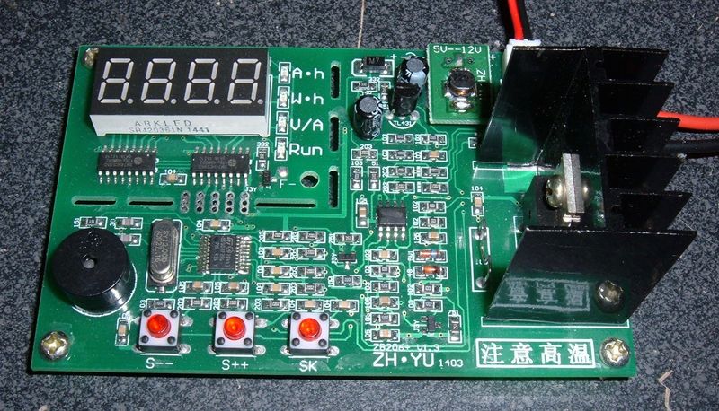
Fortunately, for a two lead BMS (positive and negative), I can simulate a healthy battery without too much trouble. Set my DC power supply to something in the pack voltage range, hook it up, and check it out!
Please note: I am NOT trying this with the battery attached. The battery (which is stone dead) has been removed, and I’m testing with the bare leads to the BMS. I’m not trying to charge the battery. Don’t do this and try to charge a stone dead battery, because it’s not safe.


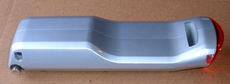
The BMS seems good! It beeps at me and the tail light comes on. This is about as good as I can hope for!
Building the Modules
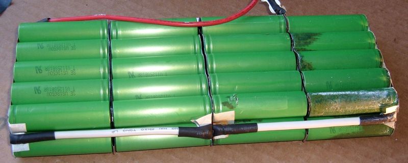
To rebuild the pack the way I want to, I need 4 11S modules. Things start, as they always do, with a box of batteries.

To line the cells up, my welder helpfully came with a cell jig. I don’t actually know where to find these as standalone objects to purchase, but they are most certainly useful! Once they’re lined up, the hot glue gun comes out and they’re glued together.

A bit more hot glue later, and all 11 cells are attached firmly to each other. This is a remarkably strong cell configuration once glued together.
The pack didn’t come glued together. It relied on the welded strips to hold the cells together. This worked fine, but I prefer things to be stronger (and the configuration will be different, so I can’t rely on the stripping for structural strength). Glue it is.

Once things are glued together, the spot welder comes out and the strip gets welded in place. You’ll notice I’m using the trapezoidal ends on the strips again. This is to prevent the sharp corner from punching through the positive protectors and shorting to the negative casing. That’s just too exciting for my taste. I’m a very boring person when it comes to shorting out batteries.
Once both sides are welded, I’ve got a 11S cluster ready to go, except for the end tabs. If you’re doing this, please be sure you don’t reverse the direction of the tabs on one side and end up with a bunch of dead shorts between two cells. You’ll only get through the first one, but I hear that it’s also incredibly exciting. Something about venting, flames, thermal runaway, and a really bad time.


Finally - all 4 modules are welded up and ready for the next step.

Connection Tabs & End Insulation
Despite what some people insist on doing, you can’t solder directly to 18650 end caps. All the manufacturers say not to, and it dumps a lot of heat into the cells that shouldn’t be there. I can touch one of the ends immediately after welding to it and it’s faintly warm to the touch. You might not want to try that with soldering onto the battery.
So, I need connection tabs to solder to. I also need to insulate these things very well.
At the top of the picture, you can see two strips of insulating paper used to insulate the ends of the cells. At the bottom, in red, is my connection tab protector. This adds a layer of protection between the connection tab and the plastic wrapper around the negative terminal. A short here is bad, so I want to ensure it won’t happen.

With the tab on, you can see how it’s protected by the thick insulating paper. Once the wire is soldered on, I’ll add more hot glue to keep this from moving at all.

The negative terminal doesn’t need the additional protection. It’s already soldered to the case, so the only thing it can rub through to is what it’s already connected to. I’ll secure it as well once the pack is assembled, though.

A bit more insulating paper, and the first layer is complete.

However, for the sake of redundancy and not having pack failures, I’m adding another layer.

There are now two full layers of insulating paper on each side of the module. They’ll face each other, so there are four layers plus whatever is holding the modules together. This should prevent any shorts. I do try to overbuild the packs because they’re going into a rough environment - bicycles are not a particularly gentle method of transportation, and I intend my packs to last, safely.

Pack Assembly
With all the modules done, it’s time to assemble them into a pack. This is how they need to go.

I searched for something that would hold the modules together firmly, but also would have a slight cushioning effect on vibration.
My double sticky 3M trim tape proved perfect. It’s an incredibly sticky double sided foam tape that I use in a variety of projects, and still have a huge roll of.
Two strips of it between each module looks like it’ll work perfectly.

A quick test fit before I expose the second adhesive side, and things fit wonderfully!

Excellent. One nicely stuck together pack. This thing is properly solid.

Crimp Connector Experimentation
The final step in the pack build is wiring up the connections. This requires coming from 4 tabs on each side to a single wire going into the BMS.
I’m not worried about the current - each module will only take 2-3A total. However, I do want to ensure I have a strong, safe, robust connection. And nothing works better than experimentation.
This is what I’m starting with. Two wires on one side, one on the other, and an uninsulated crimp connector barrel.

It turns out that this actually works perfectly for what I need. The crimp barrel is oversized for the wires, but as it crushes, the single wire remains in the bottom and the two incoming wires slide off to the sides. With a bit of careful crimping and forming, there’s a tight round connection that holds all the wires very firmly. This is exactly what I wanted - but it’s still not insulated.

Fortunately, heat shrink works perfectly. This is a nice bit of adhesive heat shrink tube and it insulates perfectly. As it heats up, the glue inside melts, and when the heat shrink cools, it glues to the wires, ensuring it stays firmly in position and isn’t going anywhere.
For the actual pack, I’ll double heat shrink the connections. There’s plenty of room.

Electrical Wiring
I’ve started building the actual pack wiring now out of 14 gauge wire. These are the junctions on the positive side, and are crimped and have a double layer of heat shrink tubing on them. They should be fine.

And the connections are installed and heat shrunk. I’m using a 4-2-1 join, much as you’d find on a nice exhaust header (I may rebuild ebike packs, but I’m still a car guy)!

The negative side is wired up similarly, but is “backwards” compared to the postitive side.

After the wiring is in place, the hot glue gun comes out again to secure the wiring against vibration and motion. Hot glue is cheap, and I don’t want things moving in relation to one another.

It’s alive! I’ve done the final 2 into 1 connection with crimp connectors of a different variety, and they’re heat shrunk down. The negative connection includes the thermistor, which will be properly placed later.

As a final step before inserting the pack in the housing, the top of the pack (where it faces the BMS) gets two layers of insulating paper. If you get the idea that I don’t want things shorting out, you’d be correct.

The new pack snug in half the casing.

And, about an hour later, I got here!
The pack is back together, tested as far as I can test it, and seems to work. Getting it together involved removing a lot of the black goop that held things together initially. It was a process of “Fit things, find what doesn’t fit, remove some goo, repeat.” And, eventually, it’s back together!
The pack isn’t quite as water tight as it was - I did discover some rubber o-ring type material in the groove. But, it looks like it works, and it should be a nice upgrade over the stock pack!

One other random thing I’ve learned: If the pack is chirping, warbling, or otherwise making a slightly disturbed alarm like noise every half hour or so - it needs charging! This is it’s “Please charge me…” alarm. If you’re hearing a random noise, can’t identify it, and have one of these packs - plug it in, please. Dead packs are no fun.
Thoughts & Conclusion
This pack is a pain in the ass. There’s no other way to describe it. It’s incredibly difficult to get apart, and it’s a very non-trivial pack to rebuild.
I really don’t understand why BionX went this way with the pack. A bunch of foam padding would have worked just as well to keep the pack in position, but wouldn’t have made this brutally difficult to get apart. The layout is a transition between their early packs and their later packs with a full BMS (where you do need the parallel groups), but it doesn’t seem to have worked well, based on the horror show of negative voltages.
I’m glad it’s back together. One down, one to go.
If you have one of these and it’s dead, at least you know it’s rebuildable. Though, it’s not going to be cheap. The labor required to rebuild this pack is very significant, and the pack will never look the same again.
Comments
Comments are handled on my Discourse forum - you'll need to create an account there to post comments.If you've found this post useful, insightful, or informative, why not support me on Ko-fi? And if you'd like to be notified of new posts (I post every two weeks), you can follow my blog via email! Of course, if you like RSS, I support that too.