
Two weeks ago, I talked about a bunch of “ways that didn’t work” for building high quality, rugged audio cable. This week, I cover the other side: How to build your own high quality rugged audio/lighting cable, for about the same cost as the cheap stuff from China!
I’ve set out to solve quite a few problems here, mostly based on real world experience with repairing broken cables from a 3 year old church plant. Plus, as is typical for me, far too much reading on cables, and a moderately decent understanding of AC waveforms. It wasn’t my strong suit in college, but I know enough to understand what I’m reading.
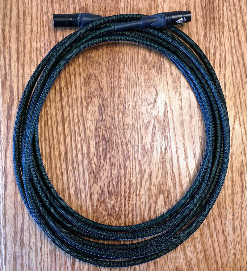
Given that, I’ve created what I think is a really, really good XLR/DMX cable. It’s based around a high quality, US manufactured cable, with additional strength, good connections, and built in “Tourizing” for additional strength.

Cost on a 25’ cable for all this? $30.
Interested? Keep reading!
XLR? DMX? Why does it matter?
In theory, XLR and DMX cables are different. The DMX-512 spec explicitly says that you cannot use a three pin connector - you need a 5 pin connector. But, they then go about using 3 of 5 pins, leaving the remainder for “future expansion.” Manufacturers of hardware caught on pretty quick and started using 3 pin XLR connectors (typically used for mic cables), which work perfectly fine for DMX hardware. It’s convenient, too - you don’t have to keep two cable types around. XLR? DMX? They’re identical connections, just plug the cable in and go! It works often enough, too!
What’s the problem? Audio cable needs to handle signals up to about 20kHz. DMX cable needs to handle square wave transmission at 250kHz - which means, realistically, you need to handle quite a few harmonics above that (into the MHz range) to get a good signal through.
DMX cable makes great audio cable. Audio cable? Well, it will probably work as DMX cable, at least for short distances. Longer? Good luck! When will it glitch out? Some inconvenient time, of course.
So, if you’re going to use one cable for everything, doesn’t it make sense to use cable that can actually serve both duties?
Rugged Cables: Touring Duty
Having established why one might want DMX cable for generic cable, the next problem is more physical. Cable strength. Literal, physical, cable-to-connector strength (and cable strength). Even audio people sometimes miss the tab and grab the wrong part of the cable. Touring cables are wound up, tossed in a cart, hauled around, banged along the road, stepped on, and generally get abused quite a bit more than fixed run cables - so it’s a good idea to make them stronger.
Also, the Belden cable is a rather vivid green (it’s sort of a “toxic radioactive slime” green). Not ideal, visually.
I’ve improved both areas by using a nylon cable braid/weave around the outside of the cable, then heat shrinking it to the ends (with adhesive heat shrink). This provides extra strength, extra wear protection, and some torsional rigidity as well. If you’re not familiar with the over-under style of winding cables to prevent them from twisting, this cable requires it.
Having worked out the build details, I’ll walk you through how to build something similar to what I’ve got!
Parts List
I’m going to assume you’re building in 25’ lengths, because, well, that’s what we build in. It’s a good standard length for a cable, and proves my point in terms of cost. You do need slightly more than 25’ of the braid, because it’s stretched a bit around the cable (perfectly fine), but that means you need more than 25’ of braid for a 25’ cable.
Parts list assumes you’re building 8 cables, since… well, also, that’s a number I’ve built.
I’m sourcing stuff mostly from eBay, but you can find stuff elsewhere (and I’ve rounded up).
200’ Belden 7200A Flexible DMX Cable: $110 (discount on multiple)
4’ 3/8” Adhesive Lined Heat Shrink: $6
300’ 1/4” Nylon Cable Weave: $60
8x Neutrik NC3FXX-14-BAG-D Female 3 Pin XLR: $37
8x Neutrik NC3MXX-BAG-D Male 3 Pin XLR: $27
And a tiny bit of solder, flux, hot glue, etc. I’ll assume you can obtain these on your own.
What this works out to, at current prices, is a grand total of under $240 for 8x 25’ high quality DMX/XLR cables - or $30/cable. Trust me, you can’t buy anything near this quality for $30.
Shorter cables will be slightly more expensive, longer cables slightly less. If you can’t get the core cable for the same price I have, it will bump the cost a bit, but it’s still entirely worth it compared to the rubbery nonsense you find from China in most other cables.
Installing the Braid
The first step is to get the braid over the cable. You’ll need slightly more braid length than cable length, as the 1/4” braid is slightly expanded over the 7200A cable. You get a nice tight fit, but 25’ of braid will lead to a slightly less than 25’ cable - plan accordingly. I’d offer numbers, but there’s no guarantee your stuff will be exactly the same, so figure it out as you go.
The nylon braid comes apart very, very easily if the ends aren’t melted together. It’s far worse than nylon rope, so have a sharp pair of scissors and a lighter handy. If the end of your braid isn’t melted properly, cut it and melt it or you’ll drive yourself nuts trying to get it around the cable.
What I find works best is two people - one to feed the braid on, one to run the “puff” down the cable to the end. Measure the cable, not the braid.
Getting the end of the braid over the end of the cable is the trickiest part. Just push the braid and cable together until it goes over - it’s tricky the first few times, but gets easier with practice.
Then, feed on a bunch of braid at the end. You’ll get a “poof” of braid - have someone chase that down the cable, and then keep doing this until you’ve fed nearly enough braid on. When you’re close to the right length (a few inches clear at each end), cut the braid, melt the ends, and finish feeding it on. Run it tight along the cable.
If it’s not centered, or you have a bit hanging off one end, push from the other end and you can “run the poof” down the cable to free up a bit extra. Trim it, and re-center the braid. Once you work out the trick, you can do this whole process fairly quickly.
Running the braid down cables is a good group activity some night - it’s not that difficult to train people in, and if you have a few people, you can get the job done quickly. My 3 year old daughter thinks this is great fun, and has asked if we’re going to “build more cables” a few times over the past weeks.
The last step should be to run your hand firmly down the cable and tighten the braid up. A glove is helpful here.
Don’t worry about the slight flare at the ends of the weave. The heat shrink will crunch that down, and it will be hidden under the connector anyway.
Heat Shrinking the Ends
To effectively hold the wrap in place and to give the cable ends something soft to grip, I use some adhesive heat shrink on the ends. This has a glue inside that melts and bonds everything together incredibly tightly - it should soak through the weave and bind it to the cable jacket, if you do things right. Plus, it has a soft rubbery surface that the cable gripper can really bite into (more so than the somewhat slick jacket on this cable).
The measurements provided are what I find works for me. You may end up with something slightly different, but I’d suggest these values until you build a few.
Cut your heat shrink tubing to 3” long. This is a good compromise between grip (longer is better) and end flexibility (shorter is better - you can start bending closer to the connection). If you have some cable that needs to bend tightly at the end, you may try shorter sleeves, but… really, you should also stop doing that to cables. It’s really hard on them.

Make a few marks on the cable. You want a mark 1/2” past the end of the sleeve, and 1” past the end of the sleeve.

Depending on how tight your shield is, you may want to wait until after you get the heat shrink over the cable to make the marks. But, run the heat shrink over the end of the cable assembly. If it sticks, a bit of twisting usually resolves it. Push it back far enough that you can then pull it towards the end and make sure the end of the braid is tight. If the braid is shifting around as you do this, you probably need to run your hand down the cable again to tighten the braid, and probably should make the end marks after doing that. You’ll figure it out quickly.

This is the sort of situation you want to avoid - the braid has shifted relative to the marks. If this happens, no big deal - simply make new marks. But you really want the 1/2” distances pretty accurate. It gives you just enough wire to work with for termination, while still allowing the grippers in the XLR connectors to bite in and clamp down on the nylon weave instead of just the bare cable.

Slide the heat shrink out to the first mark (1/2” past the end of the weave). Apply heat to shrink the heat shrink! I would suggest not using open flame for this - a heat gun works well, or if you happen to have a hot air rework station laying around, that works perfectly. I set mine at 250C and it does a nice job without damaging the nylon or the cable jacket. Don’t worry about the small bulge from the end of the braid - it will be buried inside the cable end and won’t show. If you use a torch, practice beforehand so you don’t melt the nylon weave. A heat gun is great, and your local pawn shop probably has one for nearly nothing.

Look for the glue to seep evenly out of the ends - that means you’ve gotten the heat shrink tight and the glue properly melted. It will grip the cable tightly, and it should soak through the nylon to the core and do a good job of keeping everything at the end from moving around - at all. Which, here, is the goal!

The Neutrik XLR Connectors
There are a variety of styles of XLR ends, ranging from “cheap” to “quite good.” I use Neutrik ends here, which are on the “quite good” end of the spectrum. They’re well built, and, importantly, they use a good “cable gripper” to secure the cable in the end, instead of the far weaker “crimp tabs.”
For this build, you cannot use the regular XLR ends - you need the “fat cable” ends! These are the NC3FXX-14-BAG-D and NC3MXX-BAG, and one minor bonus of using them is that you’re less likely to get fakes. The normal Neutrik ends are quite regularly faked, but very few people go to the effort of faking the weirder variants. This is a weirder variant. You need it. When you get the units, look at the black flex band around the screw in part of the connector. The letters have a hologram embedded in them. Look for shimmering and if you see it, it’s probably legitimate.
Before starting to assemble stuff, play with the ends a bit to understand how they work. On the right, the main metal barrels hold the connectors, which have the wires soldered in. Behind those, the cable gripper uses hard plastic ridges to grab the cable. Then, on the left, the rear of the connector screws in and crunches the cable gripper into the cable. Properly assembled, the gripper transfers cable stresses into the connector body, and prevents the cable from stressing the solder joints.

Before you go any further, put the back ends over the cables! You’ll forget every now and then, and once you’ve soldered the ends together, you can’t put the rear bits on - you have to unsolder everything. It’s not a big deal, but it is quite annoying, so try to avoid having to do it particularly often.

Belden 7200A: Preparing the Cable
I went into far greater detail on the cable construction two weeks ago. It’s a very, very nicely constructed cable, with foamed polyethylene insulation around the signal conductors, a foil shield, and a nice metal braid around the outside of the foil. This is great for keeping interference out and capacitance low, but it does make a cable that’s slightly harder to assemble than cheaper cables - and the assembly is a tiny bit more important as you’re starting from a good cable and good connector. You can even find a proper datasheet for the cable!

Start by trimming back the outer green jacket - back to the mark you’ve made, or right up to the edge of the heat shrink. Sharp cutters help here - you can gnaw through it with a dull wire cutter, but… just use something sharp. This will expose the outer shield braid.

Pull about half the wire braid off in one direction, and the other half off in the other. You need to trim half off, because otherwise it’s too thick to fit easily in the solder cup. Here, I’ve twisted the top half and will trim the bottom half.

Pealing the foil layer off is easier if you take a wire cutter and nip a little nick in the side where you want it to rip. Then you can just peal it off. You’re making a stress point to tear from, much like most bags of food products have. With that gone, you’ll need to split out the support strands (the thinner, off-white plastic) from the wires. Trim those off as well.

Now, strip the ends of the signal wires (only a little bit - it doesn’t have to be much to fit in the solder cups), and tin the wires with solder. Wet the wire with flux, apply some heat, and flow solder on. For the foamed PE insulation on the signal wires, it starts melting and distorting at a fairly low temperature. Play around, but I’ve found that doing the tinning with my iron set to 250C works really well. I’ll see the insulation pulling back if I leave the iron on a very long time, but I can melt my solder on without really messing up the insulation at that temperature.
When you strip the wires, if you’ve done this a lot, you’ll notice that the insulation is weird. It’s spongey and a bit squishy. That’s the foamed PE thing. It’s not difficult to work with, just different.

Installing the Connector
You did make sure the back screw on part is over the cable, right? Last chance before you have to do some rework when you realize you forgot it…
That’s OK. You’ll forget these at some point. Just unsolder the connection, put the back on, and resolder it. Sloppy, but it works fine.

Since you’re using the nice connectors instead of cheap ones, they have proper “solder cups” in the back - you can fill the back with solder and not have it run all the way down the inside of the connector. This is useful, especially when working with foamed PE insulation, since you don’t want to melt it.
I use a set of “soldering hands” to hold everything in place, though anything you can hold the connector with works. Angle it slightly head down, flux it up, and fill the three cups with solder. Now is a good time to turn your iron up, if it’s temperature controlled. I find this part works better at 300C - it’s enough faster that you actually get less heat into the wire that way.

For the male connectors, the process is the same. I like to use a spare female connector to keep the pins aligned. I’ve had the plastic soften during soldering, and the connectors don’t work well if the pins are not aligned. Don’t push it all the way in, or you’ll be doing a great amount of heat sinking that makes it very hard to solder. Just push it in enough to hold the pins in place.

It should look something like this when you’re done - a full solder cup, ready to receive a tinned wire.

XLR wiring is pretty simple. All the pins should be marked on the ends. Pin 1 is the ground/shield. Pin 2 and 3 are the signal wires - pin 2 is the positive signal, pin 3 is the inverted signal. How you wire the data lines color-wise doesn’t matter as long as both ends are consistent. I use the white wire as the main signal wire, and green as the negative signal wire (green, ground, negative… these aren’t exactly standard wire colors, but, again, as long as they match on both ends it doesn’t matter).
It helps a bit if you sort of bend the wires into position before you start soldering. It’s not required, but it does speed the process and make it easier to solder quickly.

Now, make the connections. I do the ground shield first, since it helps hold everything else in place. You want to heat the cup of solder, then push the wire in. For the shield, feel free to make sure it’s nice and hot and that the solder is flowing into the strands, but for the signal wires, be quick. As soon as the tinned wire is inserted in the cup, pull the iron off. It’ll make good contact as the solder cools, and if you’ve done it right, you don’t overheat the insulation. A small pair of tweezers can help, but I rarely need them if I’ve positioned the wires right beforehand. You’re nearly done!

Optional: Tourizing (Potting)
At this point, you can stack the connectors together and be done if you want - or, for added robustness (which is the whole point here), you can perform the “tourizing” process I’ve detailed previously and pot the ends with hot glue to help increase strength. It’s a slightly controversial thing, as it makes the connectors harder to repair if something does go wrong, but the goal is to make it so they never break in the first place. I find it worth it - it adds yet another bit of strength to some absurdly strong cables, and helps ensure that even if parts do flex in the connector, they won’t ever short out the data lines (which is really the thing to avoid).
To tourize connectors my way, you’ll need a hot glue gun. You simply fill the connector end of things with hot glue before assembling, and then (optionally) add more hot glue.
For the male ends, this is pretty easy. Put the gripper on, and slowly fill it with hot glue, rotating it around as you go so you don’t get globs dropping out. The goal is to not leak out, but to fill the whole end, and immobilize all the connections in there.

The female end is much the same. Simply fill it with hot glue.

Depending on how things fill, you may want to pre-goop the connections so everything is covered. Just cover all the connections and run the hot glue back up over the exposed cable end - you’re encapsulating everything in hot glue. Once that’s done, then fill the rest and you’ll be sure that all the important stuff is covered.

You might also consider running some hot glue down the gaps in the cable gripper. This requires a light touch, as you don’t want to fill outside the gripper and clog up the connector. It’s up to you - at this point, it probably doesn’t really add anything, but while you’re in there, may as well…

If you’ve tourized or not, you still need to put the screw back on. Crank it down tight! If you want to make your cables look different (say, by length), you can get replacement Neutrik bands of different colors to install in the middle. Customize away!

The Final Product
Once you’ve done both ends, you’re done! You should have a high quality, incredibly strong cable that’s easy to coil (if you know how to coil properly), resists twisting, slides easily to come uncoiled, and is generally totally awesome, for the cost of a regular cheap DMX cable!
I’m not saying you should use this cable to suspend a cinderblock. However, I am saying you almost certainly can use this cable to suspend a cinderblock, by just holding the connections, and have a cable that survives this sort of abuse entirely intact, both physically and electrically. This should hold up to almost anything a mobile church can dish out!
Build a few. Your sound guy will love you! Money back guarantee (on the instructions)!

DMX Terminators for less than $2
While I’m here, I’m going to be a stickler and insist on teaching you about DMX terminators as well. Any sort of signal, without proper termination, will reflect back along the line, and this can cause you all sorts of goofy problems when a reflection arrives at just the wrong time, causing flicker, glitching, and general weirdness.
You can buy DMX terminators fairly cheaply - but you can make them far, far cheaper, and if you’re this far in the post, considering (hopefully) building your own cables, then making terminators is easy. This is actually way easier than building the cables.
You can pay anywhere from $3 to $20 for a professionally built DMX terminator. I’ll offer that if you’re paying more than $2, you’re overpaying, quite badly, and should build your own. Or, pay me $5 per terminator and I’ll build you as many as you want!
A terminator for something differential like DMX is simply a resistor that matches the proper impedance of the connection (don’t worry about the details, as it doesn’t matter here). What you need are some fairly high precision 120Ω resistors. Some 1% 1/2W metal film resistors are perfect for something like this. A set of 10 should run you less than $2 shipped on eBay. You connect them across the data pins (2 and 3 for DMX), and that’s it. No active electronics. Nothing fancy. Literally a resistor connected across pins.

You also need some DMX male connectors. Here, there’s no point in spending the money on expensive ones with good cable grippers or anything - the El-Cheapo ones work fine. If you’re paying more than $1.50 per connector in bulk, look around some more. $1.50 per DMX connector, $0.20 per resistor, and you’re under $2 per terminator by a comfortable margin.

Take your resistors. Bend the wires around more or less like this. Cut them evenly so you can put them in the sockets on the connector.

Solder them into the connector - pins 2 and 3. It doesn’t matter which end goes which way, as resistors aren’t directional (and a differential signal goes both ways anyway).

After extensive research, I can suggest that putting the connector upright, so the resistor stays in from gravity is a great way to build these. Flux, flux, solder, solder, done. Super easy, super awesome. People pay how much for these?

Close it up and you’re almost done. The only problem, right now, is that you have a gizmo that, to the untrained eye, seems pointless. It’s a connector with no cable. What on earth would you want one of these for?

Therefore, the final step is to label them somehow. I used a random label maker I have around and labeled them all “DMX TERM” - even if people don’t know what that means, it makes it obvious that they’re something and shouldn’t be just tossed in the trash.

Final Thoughts
This is another one of those weird little rabbitholes I’ve gone down. I enjoy them, but they’re not always the most useful little burrows to explore. On the flip side, I’ve figured out how to build really, really good cables for roughly the cost of the cheap commercial ones, and that’s quite useful to our church. I’m aware I take weird paths through life, and I enjoy the detours greatly. Going through life buying everything you need is fine, but I prefer making things - especially if I can make an amazing item for the cost of a cheap item.
This sort of project isn’t for everyone. If you’ve got a fixed location, it probably doesn’t matter. If you don’t have anyone around who can solder, and nobody is willing to get some equipment and learn, this probably isn’t useful. But if you’ve got someone willing to spend a bit of time to build some cables, you can build amazing cables for the same cost you’re buying the cheap Chinese cables for! I hate to use the term “luxury cable,” but… it applies. They feel good, they measure out far better in terms of capacitance than the normal audio cables, and they’re rugged. I promise your sound guy will love these!
If you don’t want to build them yourself, get in touch with me. The contact form is on the right. I’d sell you a 25’ cable for $50 plus shipping, if it’s going for church plant use. We can figure something out for other lengths, and if you need custom lengths? No problem at all. If the cable fails in reasonable service, send it back and I’ll fix it. I genuinely believe these cables will survive just about anything they’ll be likely to see, and so far, in service, they are.
Comments
Comments are handled on my Discourse forum - you'll need to create an account there to post comments.If you've found this post useful, insightful, or informative, why not support me on Ko-fi? And if you'd like to be notified of new posts (I post every two weeks), you can follow my blog via email! Of course, if you like RSS, I support that too.