
It’s once again time for everyone’s favorite type of post! Tool battery teardowns! This week, I’ve got three seemingly identical batteries. They’ve got the same connections, the same dimensions (except height - the center one is a smaller capacity pack), and so one would expect them to be very much the same on the inside. Are they?

I assumed one thing going in, and was very much surprised when reality turned out to be something quite different!
The Three Packs
One of the open secrets in the power tool industry, especially battery powered tools, is that there’s an awful lot of subcontracting and rebadging going on. Despite a tool being a Makita, or a Rayovac, or whatever other official brand name is on it, there are some companies that end up building the battery packs for an awful lot of other companies - and their packs tend to look quite a bit alike between the various companies.
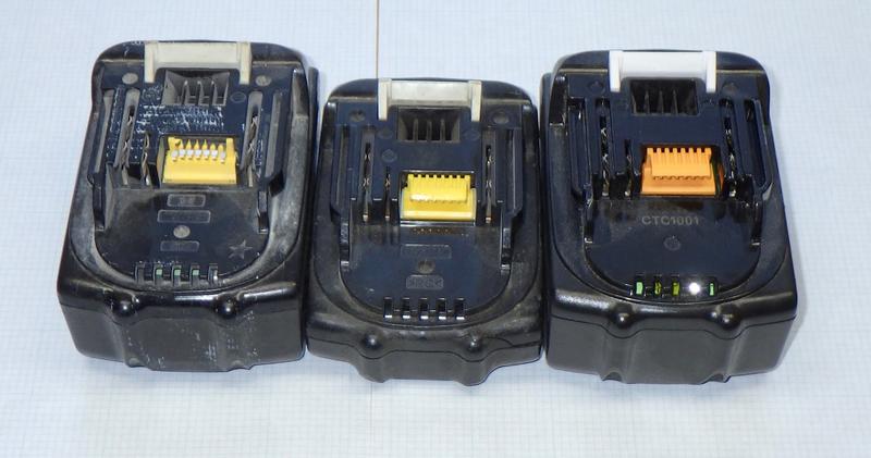
If you look at the opening picture, the three packs all have the same general shape, the same connectors, the same physical latch - they’re externally identical on the top.
Flipping them over, the similarities continue. They have the same shape, the same screw holes… the only real difference between the packs is that the ones on the left are thicker than the one on the right. Typically, this means the ones on the left will have two layers of 18650 cells, while the thin pack on the right only has a single layer - and, for these packs, that’s certainly correct.

But what I didn’t expect, from such identical packs, was just how different the insides could be!
Rayovac CTL10306 18.0V 3000mAh 54.0Wh
We’ll start with the Rayovac. This pack claims to be a 18.0V, 3000mAh pack, for 54.0Wh of energy. Note the precision! Decimal points!
The math they do works out - 18.0V at 3Ah is, in fact, 54Wh. But is it really an 18.0V pack? Well… that depends on how you do the math with the cells. If you assume the nominal voltage is 18.0V, that means a nominal per-cell voltage of 3.6V. If you use a more standard 3.7V/cell, you end up with 18.5V and another 1.5Wh. Does it matter? No - not at these energy levels.
This pack is made by Ascent Battery Supply, LLC, in Hartland, WI, if you’re curious.

Where capacity calculation creativity does start to matter is as you bump up against the 100Wh mark. That magical number shows up in a few places that are important to some people. For starters, you’re not supposed to ship anything over 100Wh through the US Postal Service. Do people? Absolutely - my Dewalt 6.0Ah pack showed up via USPS, and it’s rated at 120Wh. Whoops. Even doing math my way (18.5V @ 6Ah), you still get 111Wh - still in excess of shipping regulations.
More importantly, the FAA and TSA have a 100Wh limit on batteries - and, they point out that the final decision rests with the TSA officer about letting something through. You rapidly get into a lot of “With airline approval” sort of phrasings.
So if you wonder why Apple’s new 16” MacBook Pro with Totally Retro Futuristic Keyboard That Might Not Fail So Quickly has a spec page that lists a 100Wh battery, with a footnote carefully explaining that, no, “Actual rating of 99.8 watt-hours for 16-inch MacBook Pro” - that’s why. 99.8Wh is, obviously, less than 100Wh, so you don’t get into quibbles about “Is it 100Wh or more, or more than 100Wh?” with a TSA agent. Right there, footnote, this is allowed on an airplane, and can be shipped USPS. It’s also the largest battery you’re ever going to see in a general laptop for these exact reasons (ignoring hot swap batteries and such, which used to be more of a thing).
I’d bet decent money that if you stuck Coconut Battery on a new MBP, though, and compared the rated capacity to the actual capacity, the actual capacity would be slightly higher - and would probably push you over 100Wh. Anyone with a brand new one want to do the test and report back? Just calibrate the battery and run Coconut Battery to get the capacity! On the other hand, Apple obviously knows about this limit, so they might carefully ensure that only the actual rated capacity is advertised until the battery has worn a bit. It could go either way, but I’d still wager on it showing slightly over.
Of course, if someone wants to ship me a new one, I’m happy to do the review and testing. ;) I bought a nearly-new 2015 MacBook Pro a year or two back when I decided to replace an aging 2008 MBP, and didn’t want to fight with the stupid keyboard of the touchbar ones. It’s also rather handy being able to plug a variety of devices in without carrying a bag full of adapters…
Back to the tool battery at hand, the top side shows three primary terminals and a bunch of smaller terminals. The full depth terminal on the left is the positive terminal, and the full depth terminal on the right is the negative terminal (helpfully labeled).

On this pack, four Phillips head screws are enough to get things open. They’re buried a bit in the screw wells, but it’s no problem at all to open things up. The spring for the release even helps push the top off!
Inside, there’s a typical BMS interface board, a thermal cutoff of some variety, and, as I expected, a double height bank of Samsung 18650s.

A bit of gentle prying with plastic spudegers gets the pack guts out, revealing an interesting marking on the bottom of the pack - MK001. This would imply the “Mark 1” revision of the pack, though if you’re using a three digit identifier, you might be a bit pessimistic about the number of iterations required… This seems to be molded in - someone scraped it on the mold and it’s been pressed into every pack that mold made. It’s a bit unusual to see handwritten markings like this in a fairly modern tool pack.

The BMS board is screwed on top of the cluster of cells. The black leads extending out to the left are a standard temperature probe of some variety (almost certainly a 10k NTC thermistor) that was wrapped around and stuck inside the pack. The thermal fuse, though, is not where I would have expected to see it. It’s wired across one of the balance leads! Normally, the balance leads are just thin wires run to their respective terminals, but here, the first balance lead is the thermal protection fuse. I assume that if this trips, the BMS detects things and shuts the pack output down. Why does it need this in addition to a temperature sensor? Redundancy, I suppose. It’s a bit odd.
Another thing you might notice is that there are balance leads running to the negative terminal (as well as the negative terminal wire). On this pack, the main current handling wires are soldered straight to the full depth output terminals (so there’s always pack voltage on them). Only the half depth terminal (second from the right) is switched. You can see the switching IC for it as the black square on the right side of the board.

Overcurrent protection is handled by a thin fusable link on the positive side. The current comes through the red wire, through the fusable link, and to the positive terminal. The soldering here is a bit gross. I’m also surprised that the fusable link is a separate part and not just a thin trace on the PCB - that’s usually how something like this would be handled. Fewer pieces, fewer assembly steps, less manual soldering. MK001, I guess! But there’s an awful lot of solder heatsinking that link. I’m not sure where it would blow, and I’m pretty sure I don’t have the equipment to find out.

The single screw for the BMS board comes out, the plug for the balance leads comes out, and… well, you can either unsolder the main current handling leads, or just do what I did and snip them. This pack came to me stone dead, so there’s no real harm in doing that. Try not to short stuff.

The cells are Samsung INR18650-15Ls rated at 18A discharge. Like just about every other datasheet out there, this datasheet has a clear statement on soldering to cells.
6.1.1 The cell should not be soldered directly with other cells. Namely, the cell should be welded with leads on its terminal and then be soldered with wire or leads to solder.
6.1.2 Otherwise, it may cause damage of component, such as separator and insulator, by heat generation.
I know I tend to harp on soldering to cells a bit, but I still see people doing it, and I still regularly read datasheets saying, “Thou Shalt Not.” And, frankly, I trust the manufacturer an awful lot more than I trust some random YouTuber who relies on the tolerances of a fairly unforgiving battery chemistry and hasn’t managed to burn their house down - yet. Soldering to nickel strip spot welded to cells is fine. Soldering to cell terminals is not.

The cells are held together with the usual spot welded nickel strip. The slits serve to help drive spot welding current down through the terminal of the cell so you can spot weld with less current (and therefore less heat). It works fine without the slit, but I’m pretty sure it’s a good bit more efficient with it.
The simple squares work well for this sort of pack. Everything stays firmly connected together. There’s really nothing exciting about this pack construction. I do like to see the paper washers on the positive terminals. If you wear through the plastic wrapper on the positive side, you have a dead short to the canister of the cell (which is the negative terminal), so adding another layer of protection is frequently worth doing - especially for packs that get beat around as much as a tool cell pack.

The top of the BMS board is fairly simple - power comes through a small jack for the balance leads, since the main pack current is isolated on the sides for the terminals. You can see how the smaller large terminal is switched with the square transistor, though I’m not entirely certain what the tool side looks like. I’d guess this terminal powers a relay or something of the sort.

Flipping the board over, there’s more complexity on the back - and, matching the pack, a MK001 V9 sticker. This matches the MK001 V9 printing on the board, so I’m not entirely sure what the sticker is for. It does cover the core of the board, though - so it’ll go!

Carrying on the trend of using microcontrollers on BMS boards by tool battery manufacturers, there’s a ST STM8S003F3P6 microcontroller! According to the datasheet, this is a “Value line, 16-MHz STM8S 8-bit MCU, 8-Kbyte Flash memory, 128-byte data EEPROM, 10-bit ADC, 3 timers, UART, SPI, I²C” product. Quite a bit of capability for a little BMS! One of these days, I should really figure out how to pull the firmware off these for analysis.

A quick survey of the board also reveals that whatever failed, it failed in a way to cook R32. That’s one toasted little surface mount resistor!

The Makita BL1830 18V 54Wh Pack
Moving on, the next pack is the externally-identical Makita BL1830 pack. This, too, is an 18V, 54Wh pack - same as the previous pack. Logically, one might expect mostly identical insides.

On trying to open it, though, I run into a problem. One of the screw holes has a plug very firmly wedged in place. Plus, this pack is using “security” Torx screws. I’ve literally never seen a block plug like this on a tool pack. The security screws are more frequent, but they still accomplish nothing - anyone who cares about opening a pack isn’t going to be bothered by a security screw.
A plug in the screw well, though? That’s new - and, actually, a bit of a problem.

I could remove the plug by drilling it and putting a screw in it - or I could just remove the other three screws and rip the pack apart. It’s a teardown of a dead pack, so you can guess which path I chose.
Inside… is nothing at all like the Rayovac pack. Not in the slightest beyond the interfaces! I didn’t expect that at all - I figured they were just the same guts with a different label, but… nope! This is way different - and looks far, far nicer.
Instead of loose wires soldered around, there are formed nickel strips interfacing with the BMS. The BMS board is larger - and, in a rarity, it’s almost totally potted! There’s a rubbery substance over all the electronics to protect them from debris and liquids. I like to see this on the more complex boards, because quite a few tool packs I’ve pulled apart showed signs of liquid damage. This should, in theory, be a lot more robust against that sort of damage.

I drove the plug out - it’s legitimately designed to keep people out. You can see where I beat on it with a screwdriver. My theory was that it might have been a thin plastic plate I could shatter, but… no, not at all. Again, quite weird, and very deliberately designed to keep people from getting in the pack.

The pack guts come out easily enough - a bit of gentle prying with a plastic tool works nicely. You could use a metal screwdriver, but is it really worth messing with that on a battery pack? Use plastic.
Inside, the nickel strip holding the pack together is a configuration I’ve never seen before. It’s using indentations in the strip to contact the battery, with the plastic housing surrounding it!
Recall how, earlier, I mentioned paper washers being used to prevent the nickel strip from wearing through the plastic and shorting out the cell? This takes that concept to the extreme! Instead of a plastic covering and a paper washer, this pack uses the cell wrapper and then a massive, thick hunk of plastic! There’s no way at all for this pack to have a positive end short unless something has gone terribly, terribly wrong (and at that point, it’s probably already on fire, because the cells have been ripped open or crushed or something).
This pack is starting to seem an awful lot overkill…

The positive and negative terminals, like a lot of other packs, are always live. I wanted to disassemble it further, but it had just enough voltage (around 10V or so) left to have the potential to be exciting. Since it’s a dead pack (for some reason or another), and I’m not going to recover the cells (I just send these back to the recycling place they came from originally), I don’t feel too bad about fully draining the cells before working on it further.
A power resistor (I think this is a 5W/25Ω one) laid across the terminals and left for a while will nicely drain the remaining charge out of the cells, making it safe(r) to take wire cutters to the interconnects.

With the pack drained, I cut the BMS board off and pealed back the nickel strip (seems like 0.15mm plate) to try and open the pack further - the cells look like Sony to me, but I wanted the full identification.
With the nickel plate off, you can see rubber gaskets also protecting the area around the positive terminal - not just the nickel strip pressed down in, there’s yet another layer between the plastic and the cells.
You can also see one of the reasons I’m not a big fan of recycling cells. When you rip off the existing strip, there are still the spot weld bumps. You can’t effectively spot weld on top of those, so they should be filed down (if you’re going to spot weld as you should, and not just solder). It adds quite a bit of time to the project to smooth out the ends - but that’s the way to do cell recycling properly. Or be goofy like the Chinese recyclers and just put a slightly raised new negative terminal on - you’ll see that too.

Repeated attempts to wiggle the casing off went nowhere until I shone a flashlight down in the holes - and found a pair of screws holding the case halves together. I assure you, this overkill nickel plating, spot welded, would have done a perfectly good job holding the case together - but the designers of this pack used screws too. Getting the screws out with a charged pack would be a bit exciting - the rightmost hole would happily bridge between two cell groups if your screwdriver were a bit too wide.

Finally, with the strip removed and the screws out, the case halves slid apart. You’ve got the cell, the cell wrapper, a rubber gasket, a thick piece of plastic, and then the indented nickel strip. There’s almost certainly no way to short a cell out on this pack! I’ve seen some overbuilt packs, but I really think this one takes the prize - it’s an insanely over-engineered piece of engineering art, but I’m not at all convinced it’s actually needed.
One of the harder to learn disciplines of engineering is the concept of “enough.” Yes, it’s fun to just over-engineer something with a safety factor of 50 and beautifully machined parts, but if the actual project only needs a safety factor of 4, you’re just spending money to spend money and gaining very little in actual performance. I love over-engineered things, but I won’t pretend they’re always a good value.

One of the things I’ve learned over the years of tearing stuff down and blogging about it is that there are many, many ways to solve a problem. Some tend to be cheaper than others. Then there’s the Chinese approach - for which you make a ton of assumptions that will be more or less correct, and remove everything that’s not absolutely required by those assumptions. Some of the bike tail lights I tore down were built this way. Well engineered? Not by Western standards - but when used as they’d commonly be used, they worked just fine. And you could buy 10 of them for the cost of a single Western-engineered unit! Unregulated solar charging, NiMH cells, stuff that only worked in a narrow range of voltages corresponding exactly to the voltages you’d find on a pair of AA batteries in common service… just an interesting way to approach problems that’s opened my eyes to some of the “engineering for the sake of engineering” some companies tend to do.
This pack? This is engineering for the sake of engineering, as far as I’m concerned. Once the pack is well enough protected, additional protection just doesn’t add anything except cost.
The cells, once I got far enough in, are Sony US18650VT3s - 1500mAh, 10A rated cells. Nothing exotic, and a perfectly sane choice for a tool pack.

Finally, there’s the BMS board. This is an exceedingly nice board, well potted with a flexible rubbery substance. Unfortunately, my limited experiments in scraping the potting away didn’t get me enough removed to read the IC markings, so I don’t know what exactly is in here. If you’re good at de-encapsulating boards, I’m happy to ship this your way for experimentation!
On the far left is the thermal probe that presses against the pack. And closer in, to the left of the potted area, I see what looks like a cluster of equipment that would do pack balancing. My guess is that the left chip is a dedicated BMS analog chip, with the right IC being a microcontroller that runs the show. But without a working pack, I can’t really figure out what the charger pins do.

The back of the board is nice and clean. In the lower right, a pair of resistors are used for current sense - and you can see how the tracks on the board have been built up with solder. This is a cheap and effective way to increase the current carrying capacity of a board, and I see it quite often. I also, often enough, see boards that are obviously designed for this (bare metal traces) where nobody has actually bothered to do it. Nice to see it done (and done fairly well) here.

The Makita BL1815 18V 1.5Ah Pack
Finally, I’ve got “The same thing, but smaller.” This is a single stack pack (a row of 5 cells instead of two rows), 1.5Ah, and the same set of interfaces on top. No security plug, though!

I went into this set of teardowns thinking I’d find the same guts, plus or minus a bit. On the other related packs I’ve torn down, I usually at least fine some similarities.
These? Nope. With the guts out of the 1815, it’s yet another totally different pack. And you might notice something is missing on this one. The balance wires aren’t hidden under the BMS board - they’re simply missing, except for that one wire to the first cell (which, on this pack, doesn’t have a temperature fuse or anything in it). Unbalanced, unmonitored cells - that’s fine, right? It works for the weird spinel LiMn cells BionX used for years, but in general? No, it’s not fine! Especially on a pack with a single cell tap like this! Unfortunately, the pack is quite stone dead, so I don’t have a way to see how out of balance it was.

The bottom of the cell cluster has a rather nice molded rubber mat. Good shock protection, nicely grippy nubs for… gripping the case, I guess.

The cells in this pack are Sony US18650VTs - which… uh oh. These aren’t 1500mAh cells. They’re 1300mAh cells, or a hair less. This isn’t a 1.5Ah pack. Sorry. It’s 1.3Ah, at best. Some of the older datasheets don’t even get quite that far.
This sort of pack mislabling actually does irritate me. The pack clearly says 1.5Ah (1500mAh) out the outside, and these cells aren’t 1.5Ah cells. It’s not even within my normal “Eh, ok, you’re close…” sort of tolerances - it’s just a flat out lie. Don’t call the pack 1.5Ah when it’s not.
My guess is that the pack was originally designed with 1.5Ah cells, and at some point they switched to some cheaper cells, or couldn’t get the originally intended cells, or something along those lines. Instead of making a new pack model number, they just started tossing them in the existing pack, because, hey, nobody will know, right?
I know, and I’ve just told you. So you know too.

Moving on, we’ve got this sort of fusable link in the current path. I’m not sure where it would actually blow, and I’m not going to charge up a dead pack to short circuit it to find out. I’ll accept this as looking like the weakest link, though I’m not sure I’d really want this glowing in my pack. Someone want to do the test on one of their dead packs?

The top of the BMS board doesn’t contain much of interest. A fuse (that isn’t actually in the main current path), a rather blobby solder joint for the “cell under” wire, and a collection of surface mount components.

The underside is a lot more interesting. A microcontroller dominates the board!
What I don’t find is anything that looks like power conversion circuitry that would drop full pack voltage down to a standard microcontroller operating voltage. Just that one wire off to a single cell… which is in a microcontroller operating voltage range. It seems like they might be running the whole board off a single cell in the pack, which is a terrible idea - especially on a non-balanced pack. I’d hope that they charge that single cell more aggressively with the charger, but putting more cycles on a single cell (or cell group) because you’re pulling more power off it isn’t the way to a long lived pack. It’s a cheap shortcut to a proper design, as far as I’m concerned.
In any case, this is a fairly complex setup for a board that doesn’t do any balancing. I’m not sure why you need such a complex board to be a low voltage and high voltage cutoff, but… anyway, that’s what they put in.

The main IC is a MC908JK3E - a little 8 bit microcontroller with some onboard flash. Why? Because non-balancing BMS boards have a microcontroller these days, I suppose. I really can’t come up with any good reason to have one in this simple of a pack.

The other chip is a TL431 - a precision programmable reference. This is a common enough voltage reference, and if you want an awful lot of details, Ken Shirriff has a great post on reverse engineering the die of one of these!
I have to say, I like his style. From his post:
Getting an IC die photo usually involves dissolving the chip in dangerous acids and then photographing the die with an expensive metallurgical microscope. I wondered what I’d end up with if I just smashed a TL431 open with Vise-Grip pliers and took a look with a cheap microscope. I broke the die in half in the process, but still got some interesting results.

So, that’s what’s inside the third pack!
Final Thoughts
This post is a perfect example of “Sometimes, you don’t get what you expect.” I genuinely expected to find three substantially identical packs, just labeled differently. Instead, I got three totally different packs, with the same external connections (though I still don’t understand what it’s using all those pins for).
Until you take something apart, even if it doesn’t want to be pulled apart, you just don’t know what you’re going to find!
Comments
Comments are handled on my Discourse forum - you'll need to create an account there to post comments.If you've found this post useful, insightful, or informative, why not support me on Ko-fi? And if you'd like to be notified of new posts (I post every two weeks), you can follow my blog via email! Of course, if you like RSS, I support that too.

