
I’ve posted in the past about aviation museums, and this week is yet another one - but the difference is that this one is local! Come with me on a tour of a tiny fraction of the exhibits at the Warhawk Air Museum, in Nampa, Idaho, at the Nampa Municipal Airport!

Instead of just a random walk through the museum, I’ve broken this into general sections of interest.
Airplanes
A highlight of any aviation museum is the airplanes, and the Warhawk museum is a bit unusual here in that quite a few of their planes still fly somewhat regularly. They host the annual Warbird Roundup, and it’s not that unusual to hear the snarl of short stacked WWII era piston engines around Nampa. They host various bombers on tour as well, so I’m quite familiar with the roar of two or four large radials swinging massive props “beating up the town” on the way in. I live out under the south practice area, so I’ve also had some wonderful afternoons before the roundup watching formation practice. Quite a few thousand horsepower of supercharged piston engine overhead is a sound to behold indeed!
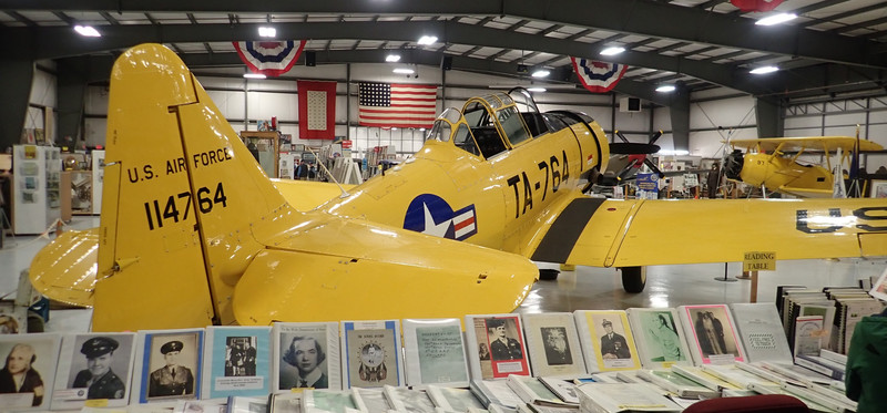
Up in the front, they have their T-6G - a mid-1930s trainer that was extensively used in WWII to train pilots in the US.

Up front, a 600hp Pratt & Whitney R-1340-AN-1 swingins a large two bladed prop. I love old radial engines, and I would very much enjoy the opportunity to fly one, if anyone happens to have one coming through the area with a spare seat…

if I’m not mistaken, the black fluid-fitting looking lines are for the fuel injection nozzles in each cylinder head. Fuel injection is not exactly new in aviation engines. The late radials were even direct injected.

You also can’t miss the rather bright Fokker DR-1 replica on exhibit. While none of the original ones exist, there are a variety of replicas floating around. This was the Red Baron’s preferred plane, and was quite deadly in the hands of a skilled pilot (partly because it was rather unstable and therefore eager to turn).

Next, a vivid yellow Naval Aircraft Factory N3N sits in the front section. Again, a 1930s trainer, built by the Navy. This one doesn’t have a cowling - perhaps for ease of maintenance. Most later radial engine aircraft had a NACA cowling of some variety, as they improve engine cooling while rather radically decreasing drag in the process. They really are a win-win!

A bit further back, if you prefer the roar of a Merlin V-12 over a radial engine, they’ve got a P-51. You may notice a few drip pans and a bit of an oil spot on the floor - again, an awful lot of their piston fleet is in flying condition. These aren’t just static exhibits, they get up and fly a few times a year! Up front, nearly 1500hp of V-12 Merlin engine.

If you’re planning to come, plan to take a while. There’s an awful lot to read around the exhibits that takes some time to get through. Behind the Mustang, you can see one of the several hanger doors that allow the planes to get out into the sun and air.

Have you ever looked at a warbird and thought, “Well, yes, wheels are nice, but how would it look on skis?” At least the the P-51, it’s been tried, with at least reasonable success - though some buffeting at speed. Again, plan to take your time and read through stuff.

The museum has two main sections of the hanger. The front is the WWII and prior section, and the back is more the early jet age (though there are still some WWII piston planes back here). They’re trying to add another section to the museum for yet more modern stuff. As you head back, you’re greeted with the distinctive pointy inlet of a MiG-21 - and the rest of the jet behind it. These, as far as I know, aren’t flying - though plenty of countries are still flying modernized MiG-21s. They’re not long ranged, but they’re still a capable Mach 2 fighter.

Reflecting a slightly earlier and subsonic era of Soviet aviation, there’s also a nice MiG-15.

The American side has a rather hard to miss F-104. It’s called, with reasonable cause, the “Missile with a Man in it,” and it’s long, very pointy, and has an alarming small wing area.

It’s really not a trick of perspective in the previous shot - the wings are really very tiny. You might expect an absurd takeoff/landing speed, and you’d be right. For a normal takeoff, rotate at 170kt, lift off around 190kt. The F-104 has a “blown flap” system, in which air from the engine’s compressor is vented, at high pressure, over the flaps. This improves boundary layer attachment, and allows you to do things land at a mere 165kt or so, depending on weight. Of course, if your flaps weren’t working, or your engine was out (so no blown flaps), touchdown speed was far higher - somewhere in the range of 240kt (or 267mph, if you prefer). That’s sizzling right along. It’ll also do Mach 2 up high, and will apparently, if you care to, cruise at 73,000 feet.

You’ll often hear that the F-104’s wing is so sharp it needs a leading edge protector. It is, in fact, that sharp. You’ll hurt yourself in a hurry on it (and probably dent it in the process, if you hit it with something harder than flesh). They come with a wing protector - and I can only imagine the flight performance with it installed is “Not today.” It’s only barely got more wing area than a Cessna 182, while weighing in at almost 10 times the takeoff weight…

Representing the subsonic American era, there’s also a nice F-86. It’s a good bit larger than the MiG-15 next to it.

Next to it, a few “training system” boards are on display - one for the main hydraulic system, one for the main landing gear, and one for the nose gear. I’ve not seen this sort of display before, but it’s a really good way to display the system in a “hands on” sort of way - this is a great way to be able to trace flows, see how systems interact, etc. It’s not only useful for mechanics - it’s very useful for pilots to have an understanding of what works how, especially if you’ve been shot and are trying to reason about what might still function to get you back down safely with a usable airplane.

Also in the back, a Huey. They’re not called choppers anymore.

There are also a few slower movers back here. This is an L-19 - a lightly modified Cessna 170. It’s got a 210hp O-470 up front, which is rather more horsepower than the stock engine. Normally, a fixed pitch prop on something like this means you can either climb fast or go fast, not both - but 210hp really does solve most problems, and I expect this can go when prodded. I’ve got a bit of time in a T-41C, which has the same engine in the 172 airframe, and it got up and went!

There’s also a P-40 back here. Again, it’s stored by the hanger doors so it can go fly every now and then. The other P-40 was in maintenance when I visited.

You can see the positions for the six claws - three on each wing. To the left is what I can only describe as a “prop cart” - it’s a railer that stores a few props off the ground for transport around. To the right, you can also see the F-84 - I wasn’t able to get any great angles on it.

Airplane Cockpits
In addition to the airplanes on display, they have a few cockpit exhibits floating around. The first is a B-24 cockpit, and they have a ball turret form one as well. They’re just on pallets right now, awaiting a better exhibit.

There’s also the oddly standard aviation museum staple, an F-111 cockpit/ejection pod. To deal with high altitude/high speed ejections, or low altitude/high speed ejections, the F-111 kicks out the entire cockpit pod in something that has to be rather violent.

The ejection sequence varies, but it kicks you up and out, rather violently. If you’re interested in more details, the internet provides!

Aircraft Models
Throughout the museum, there are a lot of models of planes as well. Plenty of display cases filled with models of just about anything that ever took to the skies, and plenty of things that never left the drawing board. Shortly after entering, there’s a rather large wooden B-29 model hanging overhead! For reference, the tail on the B-29 is about 43’ wide. The wingspan on the yellow T-6G you see on the way in is 42’.

But the most interesting exhibit is actually the paper models! I had no idea these were a thing, but there’s a huge collection of papercraft airplanes out there, and you can buy the models to print over at www.fiddlersgreen.net if you want! They range in size from single sheets of paper to some rather large and complex models that are a few feet long!

The top two shelves here are all paper models. There’s an impressive diversity of options you can build if you care!

Other Exhibits
There are quite a few other exhibits through the museum. Some of the more interesting ones:
Trench art. These are random things, built with “That which was laying around.” It’s somewhat unclear, at least to the people I talked to, how much of this was built during the war vs after the war, but it’s certainly some interesting lamp designs you’re not too likely to see elsewhere!

If you’ve got any interest in old radio transmitters and receivers, there is quite the shelving unit of radio gear from throughout the military’s history.

I enjoy the random aviation art any good aviation museum has.

I can’t help but think some of the WWII “Anti-Propaganda” advice remains a good fit for today’s modern social media world of manipulated outrage. Unfortunately, manipulated outrage is profitable for ad views. Remember, be a good little set of eyeballs with an attached wallet and vote!

Well, good thing we know better than all this archaic wisdom by now! Now we’re told to drain our savings and take on debt to go and stimulate the consumer economy. Buy the things you know won’t last or can’t possibly last (cough IoT), because that stimulates the GDP numbers! It’s fine, it’s all made in China, that one basket is really too big to possibly fail for our eggs.

Vinyl was cool back in the day, and it’s still cool now! This is a mechanical turntable with a diaphragm at the needle end and a sound tube down to the cabinet underneath. I’m not sure I want to know what the stylus pressure on the record is, though.

Some bikes from WWII that could still easily be used today. Low Tech Magazine has a recent article talking about bicycles and how they’ve gone very far away from the older, simple, long lived, generally maintainable sort of thing into the “very proprietary and tech” things we see far too much of today.

And, finally, a B-29 APU. Listen. If you’re ever tempted to hang a gas can above one of these while trying to fly a bomber off a glacier, don’t.

Piston Engines
Now for the best part of the museum, in my opinion: The engines. The Warhawk museum has quite possibly the best collection of sectioned aircraft engines I’ve ever seen, and quite a few more on display that aren’t sectioned. This is a nice collection of early RC aircraft/drone engines. The lower left one has a built in transmission for contra-rotating propellers, which is a halfway decent way to get rid of P-factor and various other “interesting” aspects of propeller driven aircraft. If you’re wondering about the lack of valve gear on top of the cylinders, it’s just because these are all two stroke engines.

Going into the full sized engines, this is a Curtiss OX-5 - an early 1900s water cooled four stroke V-8 aviation engine, making roughly 90hp. The early engines (for both aircraft and cars) had external valve gear - a valve cover wasn’t a thing yet. This made for easy maintenance, but it also meant that the engine (and everything else around it) tended to get rather dirty, rather quickly. If you want more information, there’s an OX-5 club. with plenty of additional information. One interesting feature is the valve gear - it’s a combined pushrod for the exhaust valve and pull tube for the intake valve, nested inside each other. The bronze colored rocker arms are pushed up to open the exhaust valve, while the pi-shaped arms for the intake valve are pulled down.

Intake and exhaust flow were not yet well understood in the early 1900s. Lots of right angles. Better than I’ve seen on some of the cars of the period, though. The cylinders were all individually bolted on, which is fairly standard for aircraft engines - but they’re also water cooled, which isn’t. Fortunately, the engine isn’t making that much power. It’s also one spark plug per cylinder, which had to have made for some interesting stories when the ignition system quit. More modern aircraft engines are two cylinders per plug, with independent ignition systems for each (though certain engines have a combined driveshaft for both magnetos…).

Moving forward from 1915 to 1930, this is an Allison V1710-81. This engine powered the early P-51A, before the (rather superior) Rolls Royce Merlin V-12 drastically improved high altitude performance in later models. Adding 4 cylinders over the OX-5, the 1710-81 is rated at 1000 horsepower for takeoff, and 860 horsepower continuous. The left side here has the carburetor (black box on top), the supercharger (large round thing), and various other bits of the accessory side of the engine, with the propeller being mounted on the far end. It’s a rather dramatic development in 15 years of aviation engine work, but that’s the sort of speed of improvement we had going at the time!

Mmm… carburetor linkages! As you can tell from the oil leaking, this isn’t an emptied out display model. I expect this one would happily light right up if you put exhaust stacks on and added fuel!

For scale, the piston in the lower right. It’s a 5.5” bore, a 6” stroke, and if you do the math, that works out to 1710 cubic inches (you can see where the name comes from), or, for those used to thinking in metric displacements, 28 liters.

Now it’s time for all the sectioned engines! If you look carefully, you’ll also find an exhibit of sectioned propeller governors. These regulate the blade angle of the propeller such that the engine is always turning at governed speed - regardless of throttle position and airspeed. Constant speed props are awesome to fly behind.

A very clean Le Rhône rotary engine is up in the front of the museum. This was an early rotary engine - not the later style radial engine. What’s the difference? On a rotary engine, the entire engine crankcase - cylinders and all - spins while running. It means you’ve got good airflow to cool the engine, but it also means you have incredible gyroscopic forces. It also meant the oiling system was rather hostile to the pilot…
Take a look at the valve actuation system. There’s one push/pull rod, and it’s pushed to operate the exhaust valve, or pulled to operate the intake valve. This worked, but wasn’t very long lived as a design as it didn’t permit valve overlap. Again, exposed valve gear.

Actually, the exhibit has a great writeup on it. Seriously, two gallons an hour of castor oil in your face. Being clogged up was not a problem!

Moving forward a bit, people rapidly figured out that having the whole engine rotating was a bad idea, so the radial engines, while looking similar from the outside, had stationary cylinders in operation, simply rotating the crankshaft internally. This is a R-985-AN, also known as the Wasp Junior. It made 450hp, and was one of the bog standard radial engines of the early aviation age. By 1930, engines were fully enclosed in operation, with rocker covers and valve covers keeping all the bits and pieces inside a sealed environment, well splashed in oil.

Go forward another 15 years, from 1930 to 1944, and you get the Pratt & Whitney R-4360 Wasp Major making, in various trims, somewhere around 4300 horsepower. Start stacking radial engines behind one another on a common crankcase, put a giant supercharger in front, and you end up with an awful lot of moving pieces - but, after some development, an incredibly reliable engine that could run for thousands of hours in the hands of a well trained flight engineer.

While the museum neither has a full size B-29 nor a B-36, this remains one of my favorite aviation images. On the left, the B-29 looks like a cute little toy compared to the B-36. If you’ve ever been around a B-29, they’re not small. The SAC museum west of Omaha has a B-36 and a B-52, and the B-52 looks cute. The B-36 is a big airplane. Six turning, four burning! Or, per some crews after more than frustrating missions, “Two turning, two burning, two smoking, two choking and two more unaccounted for.”

Going down in size, there’s a smaller Lycoming O-480, a 340hp general aviation engine. It’s a six cylinder horizontally opposed air cooled engine, and shows the features common in most of the smaller aircraft engines. On the left, the crankshaft is visible at the bottom of the opening, with the camshaft sitting at the top. That runs the pushrods up to the top of the cylinders, with independent pushrods and rocker arms for the intake and exhaust valves.

Two valves per cylinder, two spark plugs per cylinder, one piston per cylinder. Ideally, both spark plugs are firing, but if one half of the ignition system quits, the other half should keep the engine turning and making power until you get down to the ground. Interestingly, someone has gone to the trouble to section the spark plug here - I don’t think I’ve ever seen that before!

Down below, the intake system for the engine actually flows through the crankcase. The carburetor is bolted to the bottom of the engine, and receives quite a bit of heat from the oil pan. If you wonder why some aircraft engines are more prone to carburetor icing than others, this would be one of the sorts that isn’t very prone to it at all.

Sectioned Jet Engines
There are also quite a few sectioned jet engines to be found scattered around, and I’ve shown off a few samples here.
Starting out, this is a General Electric J-31 - the first American jet engine to be mass produced, and used in the Bell P-59. First run in 1943, this is a centrifugal compressor based engine making 1600 pounds of thrust (no, that’s not much). You can easily trace airflow from the right to the left. The large round wheel on the right is the compressor, sucking air from both the frontside and backside. If you see this sort of “dual intakes covered in mesh” setup, it’s almost certainly a centrifugal compressor. Air is squeezed and kicked out into the burner tubes surrounding the engine - you can see a complete one in the bottom, and a sectioned one at the top. Air flows back, entering the burner can through the holes around the outside (and cooling the can as it flows around it). Fuel is injected and burned, and it continues around the curve, tightening before impinging on the single stage turbine wheel and heading out the back.
Efficiency on these is “not amazing.” Count the number of degrees of airflow direction change through the engine - coming from the front (right) of the engine, I get about 720 degrees of airflow direction change through the engine.

The compressor wheel has a but of a curve on the intake sides to help scoop the air in. I wonder what those looked like after some hours of operation in any sort of dusty environment.

The closely related Allison J-33 is another early American jet engine, with the main differences being “But bigger,” and straight through combustors instead of the reverse flow ones in the J-31. Air doesn’t have to do a bunch of direction reversals after being compressed - it continues a rearward flow through the combustors on the way to the turbine and exhaust. The result? About 4600 pounds of thrust - or, 5400 pounds “wet.” This engine supported water injection for takeoff thrust augmentation. By injecting water (usually a water-alcohol mix for freezing reasons) into the engine before the combustors, the mass of the airflow is increased, and the intake air is cooled significantly after the heat of compression. This allows the engine to burn more fuel while still keeping the turbine inlet temperatures below the limits. A typical jet engine is limited by turbine inlet temperatures, and anything you can do to burn more fuel before hitting those helps you out. Or, later on, we worked out that you just burn more fuel after the turbine (in the afterburners), and skip the whole problem. Water injection works, though it does tend to leave a column of black smoke behind the engine.

The General Electric J-47 is an early (late 1940s) axial flow jet engine making around 6000 pounds thrust. Instead of the centrifugal compressor of the earlier engines, a multi-stage axial compressor (on the right) squeezes the air for combustion before a set of straight through burner cans inject the fuel and get things going. A single turbine stage at the rear extracts the energy to spin the compressors.

It’s a bit hard to see the angle, but between each row of compressor blades, a set of stators (visible in the bottom half) help redirect the airflow into the next stage. Without them, the air would just end up swirling around instead of being compressed - but the stators are curved so they capture the rotation of the air and help convert it into yet more static pressure before the next stage. Each stage of the compressor also has slightly different fin shapes and angles to handle the expected air pressure at their stage.

Each burner can has a fuel injector (at the right), but also an igniter - the spark plug looking thing in the top right is, in fact, a spark plug. These are needed to start the engine, and they’re also used in flight during times the engine might have problems remaining lit - heavy rain, icing conditions that might disrupt airflow to the engine, or heavy turbulence are often conditions when the igniters are run during flight.

Finally, representing a more modern engine (axial flow,multi-spool) from the early 1950s, the Pratt & Whitney J57 makes 11,000-15,000 pounds thrust depending on variant, and can have an afterburner. Instead of each burner can being a separate entity, the combustors here are all in a single pressurized ring, which improves various aspects of operation. You’ll notice three distinct turbine disks on the left, and this engine had two separate “spools” - turbine and compressor pairs. As engine pressure ratios increased (improving performance), a single stage compressor could no longer handle all the airflow requirements from startup through full power operation, and splitting the engine into multiple rotating elements is one way of solving the problem.
The first (rightmost) turbine wheel drives the seven high pressure compressor stages, and the two lower pressure turbine wheels on the left drive the nine low pressure combustion stages.

Taking a closer look at the compressor section, you can see the high pressure compressor stages on the left, with lots of fairly small fan blades. Between each set of blades is a set of stators that help redirect the airflow - without them, the air would just swirl around and not actually get compressed. On the right, the low pressure compressor stages are larger, and more or less serve to swallow air and feed it, in some reasonably sane pressure and quantity, to the high pressure compressor stages. A modern turbofan engine will typically have three stages, with the last turbine stage driving the bypass fans (that generate most of the thrust).

If You’re In the Area…
So, if you find yourself in the Nampa, Idaho area, and like your airplanes and war museums, stop in at the Warhawk museum! You can do a quick visit in a few hours, but if you want to read through the copious material available, talk to the (very knowledgeable) docents, and properly take it in, plan to spend the day. Small children probably won’t have the attention span for that, but there’s a vast wealth of material here to go through!
And if you do drop in, let me know! There’s a great little restaurant just down the street (the Tower Grill) overlooking the runway at the airport, and I’m always up for an excuse to grab a bite and watch airplanes!
Comments
Comments are handled on my Discourse forum - you'll need to create an account there to post comments.If you've found this post useful, insightful, or informative, why not support me on Ko-fi? And if you'd like to be notified of new posts (I post every two weeks), you can follow my blog via email! Of course, if you like RSS, I support that too.


