
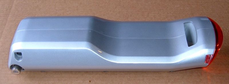
If you missed part 1 of the Trek Valencia Ride+ battery pack teardown, you should go read that first.
To recap: A battery pack, bound together by a lot of adhesive, difficult to get apart, and I didn’t feel like pulling the actual battery pack apart after I got it out and discovered it was a corroded mess.
Now I’m going to dive into the corroded mess and see if I can figure out what’s going on.

Read on to join me for a lot of battery pack photos!
The bulk pack voltage is a whopping 0.421v. This pack is dead, Jim_._ It’s not even nailed to the perch.

The positive end is covered with some black plastic insulation. Not for long! A bunch of chipping away of brittle plastic, and I’ve got… this.

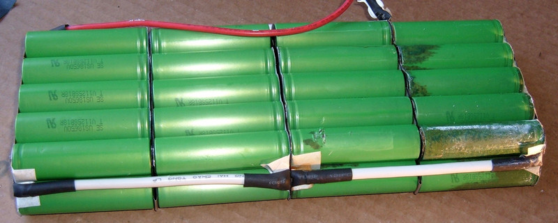
It’s pretty clear what they’ve done at this point. The pack is 4P battery strings, connected together in an interesting manner, with a lot of custom cut nickel strip and additional wires to bridge things to the next set of 11 cells where needed.
I think someone wanted an excuse to play with their shiny new custom nickel strip cutter, though. There are a lot of different strip shapes for this one pack.
I like the use of fiber insulation under the nickel strips. This is a definite evolution on the earlier packs.
The positive wire is soldered to the nickel strip, clear of the positive terminal. Excellent. This means they’re not dumping heat into the battery trying to solder directly on top of it. With the heat shrink removed, I can just desolder this and make my life easier.
Also, you can (barely) see on the top cells that there’s a slit in the nickel strip over each cell. This improves the welding, and allows for a better weld joint with less current (as it forces all the current to go through the weld points and the end of the cell, instead of just bypassing through the strip).

With the cell chunks separated, the pack arrangement becomes clear. It’s functionally just a long pack that’s been folded, with the connections bridged as needed using large wire. If you imagine straightening out the pack, the ends currently connected with the white wires would be touching, and would be able to be connected with nickel strip like the joints are. It’s a 4P11S pack, bent up into a weird arrangement.

Taking a closer look at the corroded end… it’s just gross.

So, of course, I’ll start at the other end.
The heat shrink comes off the bridge wire, and… ew. That’s not a great looking solder joint.

This is the same solder joint after I took a while trying to remove it. I understand why it’s not great - the huge wire just sucks all the heat out of the joint, and it’s basically impossible to heat it up enough to flow solder. I don’t actually know why they used such a large wire gauge for these connections. It’s really not needed. The thin bit of nickel strip is the high resistance point, not the wire.

So I just snipped the end off. That’s fine for a pack teardown.
You can see some of the teardown progress here. That plastic insulation is a royal pain to get off!

Another set of neat shapes here in the custom cut nickel department. Though, I admit I have no idea why they didn’t just use a sheet. I guess if you’re cutting the slits in the middle, you may as well cut other stuff?
It still feels to me like someone got their hands on a super fancy nickel strip cutting machine and set out to justify it, though.

About this point, while I was chipping the black insulation off, I thought about how nice this would be to work on in the summer, with all the heat so the plastic isn’t brittle. About this time, I had to move my leg away from my dual 500W shop lamps before they singed hair off. Fortunately, I can do synergy with ideas and conclude that I have a great heat source for heating the plastic. And this made things much easier.
LED work lamps are nice, but there are some things that 500W of halogen fury is better suited to, and this is one. Once warmed up, the insulation came off much easier!

So, I kept going. The endless variety of nickel strip patterns are entertaining, if a bit annoying from a “I’d like to actually rebuild this pack” point of view.


And, it’s time to get some details of the corroded end.
It’s really, really nasty.


I’ve got the pack totally unfolded now. And I am incredibly curious about these corroded cells. So, out comes my voltmeter! I hook it up…
… and then double check that I’m testing it the correct way. You know, red to positive, black to negative. Then scratch my head and test again. Nope. Still showing -276mV. Negative. This set of cells is 3v below the minimum recommended voltage of 2.7v.

And they’re gross.

Oh, yes. The green wire running along with the negative wire goes to a thermistor. So it’s just like the other BionX packs I’ve worked on.

Per Cell Voltages
After seeing the horror show of negative voltage, I wanted to see what the other cells were at. So I tested. By parallel cell region, starting from the negative side:
-1.1mv, -197mv, -280mv, 1.0v, -0.5mv, -1.2mv, 0, -0.4mv, 0.2mv, 0, 0.676v
That’s an awful lot of negative voltage in there. Only two regions are above zero by any meaningful amount.
How does this happen? It involves discharging a cell, then forcing current through it after it’s drained, and not in the useful charging direction. If a set of cells is weak, this can happen if you keep draining a pack (and the BionX BMS absolutely does keep draining a low pack). It can’t happen from self discharge, as far as I understand things - it has to involve an external load.
But, in any case, the pack is quite dead.
Pack Summary
This pack is a 4P11S pack using the same Sony US18650V cells as the older BionX packs. In contrast to the older packs I’ve worked on (which are series strings paralleled together), this is a bunch of parallel strings in series. This is a more standard pack arrangement, especially when you use a BMS that allows for balancing and low voltage cutoff for each voltage region, not just the global pack voltage.
Which this pack isn’t using. I hear the newer 48v packs have a proper BMS, and I look forward to tearing one down in a few months if all goes well.
As to what killed this pack? I’m not sure. Either a loss of capacity caused the cells to get driven too low, or they got out of balance. In either case, it probably got worse as time went on.
This is the downside of not having anything but a bulk voltage sensor - you can’t detect things like this early.
I’m impressed with the Sony cells, though. Despite this abuse, they didn’t do anything harmful. There’s no evidence of heat in the pack.
I’d like to test the cells and see what sort of capacity they have left after this abuse, but I’m not going to do that until I have a place I can safely have batteries run away. So, don’t expect that set of tests for a while.
Fortunately, some testing shows the BMS is still alive and responsive (for at least sanity check levels of alive), so I can rebuild it. But that’s a future post.
… seriously, negative voltages. That’s just not right. Especially not this many.
Curious as to how I rebuilt it? Keep reading! Trek Valencia Ride+ BionX Battery Pack Rebuild
Comments
Comments are handled on my Discourse forum - you'll need to create an account there to post comments.If you've found this post useful, insightful, or informative, why not support me on Ko-fi? And if you'd like to be notified of new posts (I post every two weeks), you can follow my blog via email! Of course, if you like RSS, I support that too.


