
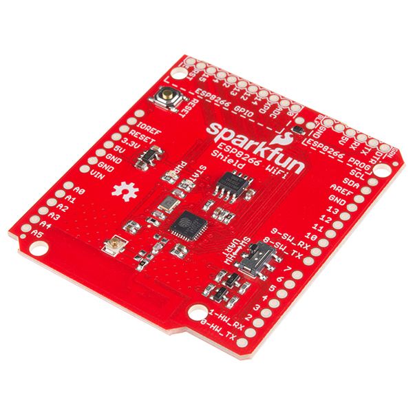
I started a project of mine with a SparkFun ESP8266 WiFi shield. After several frustrating weeks caused by a variety of issues, but mostly a bad U.fl connector (external antennas were unreliable), I gave up on that one, and decided to build my own, because I can.
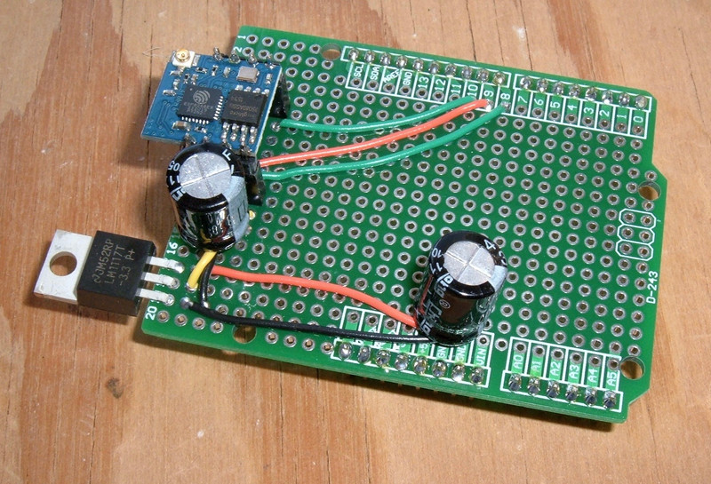
This is what I came up with - cheap (under $10), effective, and so far, quite reliable!

Read on for the construction details, costs, and a lot of suggestions on working with the ESP02 wireless modules.
The ESP02
Like anything else coming out of China at low prices, there are half a dozen things under the same name. I’ve found several different ESP02 pinouts depending on the exact module, and they don’t even all bring the same pins out - mine brings CH_PD out to the edge, but some others don’t (some of the red ones have GPIO15 run out instead of CH_PD).
About the only common thing I can find between all the ESP02 modules is that they have 4 pins on each side, a U.fl connector, and an ESP8266 jammed somewhere on the board. There are otherwise some significant differences between modules sharing the same name. So make sure yours has the pins you want, and double check the pinout for your module! I think the blue ones are all the same and the red ones are vary, but seriously, double check. There are quite a few variants out there.
Why am I using this particular module (the blue ESP02)? I need both an external antenna port (for remote nodes) and the ability to control the power state. Internal antennas are nice, but won’t work for the ranges I’m hoping to play with - I may need panel antennas for some of my nodes.

This is the pinout for mine (and almost certainly not yours). I’m not using GPIO0 or GPIO2, but it has the all-important (to me) CH_PD pin brought out.
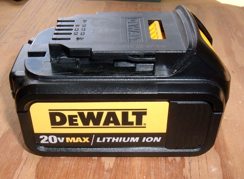
CH_PD is the powerdown pin. Bring it high (~3.3V), the chip powers on. Drag it low (~0V), and the unit powers off. Since I’m putting this into a solar powered box that lives in my lawn or garden, low power modes are really important. There’s no point in keeping a 50mW radio powered up 100% of the time if I’m using it once an hour. More importantly, I don’t have the power budget for that in the winter.

Attaching Headers to the ESP02
The ESP02 form factor has 4 pins on each side with a standard 2.54mm spacing (or, for something that makes radically more sense, 0.1” spacing). I’ve got a bunch of breakaway headers that are just perfect for something like this.

Breadboards are useful for many things, including holding headers in place while soldering. Really, just find a method that works. You can do it freehand if you want as well, since as soon as the first pin is secure, the pins on that side aren’t going anywhere.

It’s not the prettiest job I’ve ever done, and it’s still wet with flux, but it’s good to go. One of these days I’ll find a flux pen that I can control…

Testing and Power Analysis
Before I actually go about putting this onto something permanent, it would be useful to test it, right?
Beyond just testing, there’s also configuring the serial baud rate. The ESP02s I got ship configured for 115200 baud - which is quite a bit faster than the software serial interface on the Arduino can reliably handle (the hardware interface is fine up there, but I’m going to run this with software serial). I need to reconfigure them for 9600 baud before I put them into a board. Also, if you store the wireless SSID/key to the ESP8266 flash, you don’t need to include that in your Arduino sketch - so there’s some potential space savings…
If you want to talk to one of these, you’ll need a USB-to-serial converter that supports 3.3V signaling (on paper - in reality, 5V is fine), a 3.3V voltage regulator (they’re not 5V tolerant for VCC, and your serial adapter won’t power them), a stripped USB cable for a 5V power source feeding the regulator (or some other way to get 3.3V into the board), and some jumpers to wire everything up.
This setup also allows for easy testing of power draw. Idle, my ESP02 draws about 45-50mA (of either 3.3V or 5V - my regulator isn’t fancy, so it just wastes the difference as heat), with a floodping power draw of around 80mA. This would be higher at a longer distance, but it gives me an idea of what I’m working with.
Powered down? 0.0mA (per my meter). I’m sure it’s drawing something, but it’s so little as to not matter.
I also learned that while you can leave the RST pin floating, it’s a better idea to tie it high. Grounding it will reset the unit (it pulls about 30mA while RST is low - so not the same as powering it down), but leaving important pins floating can cause erratic behavior - so just tie it high.

If you just want something that will just talk to it over serial (highly recommended), you can build something on a much smaller breadboard. That’s a FDTI serial adapter wired in, and power from a USB hub. I leave this board wired up and can drop a module in whenever I need to talk to one. Yes, RST is floating. It’s probably fine.

Wiring is pretty simple. Get yourself a 5V rail from a USB power cable (strip one, build one, whatever), run this into the LM1117 voltage regular, run 3.3V and ground into the ESP02. Connect the TX pin on the ESP02 to the RX pin on your serial adapter, and the same for other direction. Tie CH_PD to 3.3V, and if you’re feeling thorough, tie RST to 3.3V. You’re good!
If you can’t talk to it, try other baud rates. The initial debug output comes at 78400 baud (which is a funky, weird, off the walls rate that’s probably some fraction of the core frequency), but it will actually try to talk to you at 115200 or something a bit more standard. If you don’t see output at 78400 on powerup, check your wiring. You probably wired TX to TX. Or flipped the sides and are trying to read from the GPIO0 line…
Serial Baud Rates
Talking to the ESP02 with a serial adapter is easy enough. There are many ways to communicate with it, but the easiest is actually the Arduino software. Select the port, open the serial monitor, and you’ve got an easy way to chatter with it. The AT Command List (yes, like the old AT modem commands, if you’re that old) might be a good place to start playing around.
You must send them CRLF (“Both NL & CR” in the Arduino console) at the end of a command. They don’t respond to just a newline!
If you have the baud rate totally wrong (say, 9600 when the device is configured for 115200), you’ll see nothing but junk on powerup and it won’t respond.

Regardless of the actual “normal” baud rate settings, the initial boot sequence should show up at 74880 baud (I’m sure there’s a good reason for this, and I still have no idea what it is). You’ll see the boot up message, then garbage once it switches to the configured serial baud rate.

If you get it right, you’ll see rubbish from the boot, then “ready” (or maybe “Ready”) at your configured rate. If everything is working properly, you can send “AT” (set to “Both NL & CR” or it will ignore you), and see “OK” in response.

To reset the serial rate, send a command like, AT+UART_DEF=9600,8,1,0,0 - this sets 9600 baud, 8 data bits, one stop bit, no parity, and no flow control. You’ll get “OK” as a response, then need to set the new serial baud rate to see anything.

Power Considerations
Would you like an unreliable ESP8266 based device? Starve it of power.
It needs 3.3V, and will fry on 5V. The obvious (and wrong) answer is to try and power it from the Arduino 3.3V rail. That won’t work well (though it might work just well enough to drive you insane troubleshooting). Arduinos are generally rated for around 50mA off the 3.3V rail. If you notice my power readings from above, that’s not enough. Even some of the boards that can source more may or may not work - the chip can pull over 300mA in a brief spike at high transmit power. It needs a beefy power source, and it needs enough power to not brown out when it wants a lot of current right now.
This means building your own 3.3 volt supply for the chip. Ideally this should have some nice filter capacitors to help handle the current spikes.
I’m using a basic LM1117 fixed output regulator. You feed it up to 15V (I’ll be feeding it 5V), and out comes 3.3V - or whatever the regulator you picked up is set for. Since I picked up a 3.3V regulator, it always puts out 3.3V. There are adjustable versions - you don’t need or want those for this use case.

The regulator isn’t fancy. It dumps the excess voltage as heat. But, at less than $1 in small quantities, I don’t care. And it won’t be dumping much power. At 50mA, 1.7v of drop is 85mW - and only briefly, while I’m transmitting data. Otherwise, everything will be powered down and the regulator will be drawing nearly nothing. There’s just no point in using a more expensive voltage regulator here.
I also plan to use a pair of 470uF capacitors (because I have them laying around for things like this) - one on the 5V rail, one on the 3.3V rail. It won’t make anything worse, and they should help stabilize voltage by a lot - both in terms of transients, and in terms of ripple. Nobody ever complained about less ripple on a voltage line!
Building the ESP02 Shield
Plug type breadboards are all well and good, but they’re not going to work for longer term production use in my yard. Fortunately, these prototype shields are cheap and plentiful! Seriously, they’re about $1.50 once you add the headers. Wonderfully cheap, easy to work with, and cheap. If you screw one up? Oh well. Toss it and move on.

I decided to put the ESP02 in female headers. This allows me to easily pull the module if I have reason to do so. Because I’m going to be running 5V IO into it, I may fry it (probably not, but… maybe). Or, if I want to flash firmware, I’ll need to muck with more pins. I’m not vertically limited, so into a set of risers it goes!

The ESP02 headers are soldered onto one end, with the location and orientation mostly chosen so the U.fl header is facing out, and with enough room for the voltage regulator. Why this end? So I can do something useful with the pins on the other end, like monitor soil moisture!
The voltage regulator is hanging off the end to keep it out of the way. This location might help with cooling, but if I’m having cooling issues on this at under 100mW, something has gone badly, badly wrong with the entire system. Or I’ve wired it backwards and am trying to regulate -5V with it - which will make it rather warm in a hurry. So I hear. When soldering up a USB cable to provide 5V, don’t blindly assume things about which side is which.

Power wiring (other than the filter capacitors) is simple enough. The Arduino 5v terminal goes to the positive side of the regulator, ground goes to the negative side. The center pin (regulated output) goes to the ESP02, and ground gets continued over.

The backside shows how one goes about connecting the terminals. Solder blobs! It’s helpful to leave some excess wire and bend it over towards the connecting terminal.

Here’s where I go a bit off the rails compared to most ESP8266 shields. I’m not using voltage converters! #YOLO (there’s a kid on my lawn, but she’s not talking much yet, so I assume this is what she’s saying…) (this kid also has led to data reliability issues when the guts of my outdoor test box were strewn across the lawn…)
From the ESP8266 datasheet:
All digital IO pins are protected from over-voltage with a snap-back circuit connected between the pad and ground. The snap back voltage is typically about 6V, and the holding voltage is 5.8V. This provides protection from over-voltages and ESD.
This implies that 5V is a safe voltage - were it not, the protection circuitry would be lower.
Some other people have poked around and discovered that you can run it with 5V IO for extended periods of time without any apparent problems. The current on the IO pins, even at 5V, is in the uA range - so not likely to cause damage.
Also, I tried a resistor based voltage divider on my serial TX line and had nothing but reliability issues. So, straight 5V it is until I come up with some reason to change it (this chip suddenly dying would be one such reason, and I will certainly report back if that happens).
I’m using the same pins for software serial as the SparkFun shield, which means I can use the same code (mostly). Transmit out of the ESP02 is wired straight to the Arduino receive on pin 8, without any voltage shifting - 3.3V is a logical 1 for the Arduino, so it’s fine. Pin 9 from the Arduino (TX) is wired straight into the RX pin on the ESP02.
And, CH_PD (chip enable) is run to pin 10. I probably could run it at 5V like the others, but a pullup resistor is easy enough here, so I’m doing that.

The back is a bunch of solder bridges to link points together, and two 15k pull up resistors for the RST and CH_PD. This ensures that unless something else happens, both pins are at 3.3V.
By the way, if you were so inclined to pull up GPIO0 and GPIO2, you might want to do so with separate resistors. If you wire RST, GPIO0, and GPIO2 together, the chip won’t boot.

How all this works from the “control chip power status” side is that I toggle pin 10 between a high impedance input to power the ESP02 on (the pull up resistor does its thing) and a low output (this overpowers the pull up resistor and shuts the ESP02 down, with a whopping 2uA of current or something around there).
Finally, after all the wiring is done, I add two 470uF filter capacitors. The 3.3V capacitor is as close to the ESP02 as I can get it - distance matters, and reports indicate that putting a big capacitor close to the chip is a great way to help stability. The 5V filter capacitor is closer to the Arduino side to help regulate the voltage there. I probably don’t need it, but it won’t hurt anything.
If you want to, this is also a good point to put an input header for power. You can safely run an Arduino by supplying 5V to the 5V rail - everything else gets regulated properly, and when an Arduino is powered from USB, it’s basically just a direct input to the 5V rail anyway (fused, but your external power supply can do the same thing).
There’s a reason the space near A0-A5 is clear, and D0-D7 is clear. Those will be used for the actual sensor inputs!
So, that’s my ESP02 DIY WiFi Shield. Attach an antenna and go!

Communication & Control
It’s really quite simple to use. If you use the SparkFun ESP8266 library, it’s all set for software serial on pins 8 & 9, 9600 baud.
Controlling power you’ll have to do on your own, but it’s pretty straightforward as well. These are the functions I use.
// Put the radio to sleep: Force pin 10 low.
void sleepRadio() {
  esp8266.disconnect();
  pinMode(10, OUTPUT);
  digitalWrite(10, LOW);
  digitalWrite(13, LOW);
}

// Wake the radio: Set pin 10 to high impedence.
void wakeRadio() {
  pinMode(10, INPUT);
  digitalWrite(10, LOW);
  digitalWrite(13, HIGH);
}
One bit of advice: Disconnect the radio before you sleep, or your AP may get unhappy with the device after a while. It’s nice to say “Goodbye!” before going off the air.
Pin 10 always stays in the “low” state, and is toggled between input and output. In the input state, the Arduino pullup resistor is disabled, and the 10k pullup resistor on the shield brings it to 3.3V. In the output state, pin 10 is driven low, and overcomes the pullup resistor to drag CH_PD to 0V.
I toggle pin 13 as well, just so I have a visual indication as to the state of the radio (as the ESP02 doesn’t waste power with silly power LEDs). This doesn’t use much power, and it’s handy as a sanity check.
You’ll need to reinitialize the radio after waking it if it’s in any way “not in the default state.” That will be up to your library, though. I suggest calling esp8266.begin() if you’re using the SparkFun library a few seconds after waking the chip.
Build Costs
I buy most of my stuff on eBay - so product links go there. I also tend to buy in bulk, so prices are assuming you’re ordering a few of the items. It’ll be slightly more expensive in small quantities, but if you want to build 5 or 10, they’re under $10/ea. Shipping from China or Hong Kong is remarkably quick… most of the time.
ESP02 module: $2.50
Arduino prototype PCB: $1.20
LM1117 3.3v regulator: $0.75
Breakaway headers (32): $0.26
470uF filter capacitors (2): $0.08
4 pin header (2): $0.06
Wire and solder: $0.05
Total cost for the board: $4.90
U.fl pigtail and 2.4ghz antenna: $5
Total cost, connected to the interwebs: Under $10. You can build it in half an hour if you’re halfway competent with a soldering iron.
Final Thoughts
This is a pretty straightforward build once you have the parts. That the ESP02 acts for all the world like it’s 5V IO tolerant makes things a whole lot easier.
Hopefully you find this useful. For me, having these working is certainly useful, but not the end point. This is just the starting point! I have a lot more to add to this board, and I’m working on ways to make it a whole lot more professional looking as well. ;)
Let me know in the comments if you’ve built a shield from this!
Comments
Comments are handled on my Discourse forum - you'll need to create an account there to post comments.If you've found this post useful, insightful, or informative, why not support me on Ko-fi? And if you'd like to be notified of new posts (I post every two weeks), you can follow my blog via email! Of course, if you like RSS, I support that too.


