
I’ve been working on a wireless moisture sensor project on and off over the past month or two. My property is spread out, and I’d like to be able to keep track of soil moisture over time - with the long term goal of controlling irrigation systems automatically from a central command point. Since everything is spread out, the sensors and controls need to be wireless for both communication and power.
My initial plan involved using the SparkFun ESP8266 WiFi Shield for communication. Over the past few weeks, I’ve learned a lot about that shield. Most of the stuff I learned required piecing together things from a variety of sources - there was no one reference for it. So, hopefully it’s useful to you as well. Sadly, I also learned that the few boards I ordered have an unreliable U.fl port, and are therefore unsuited to my needs.

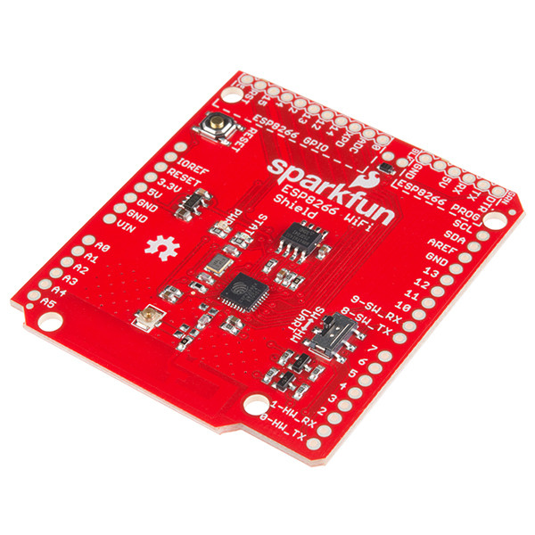
It is a good looking device, with nearly all the useful pins brought out to 2.54mm headers. Or, 0.1” headers. It exposes almost all the functionality of the ESP8266, has some nice status LEDs (power and “talking to something”), supports both hardware and software serial, has an onboard antenna, and in general is a quite nice shield for $15.

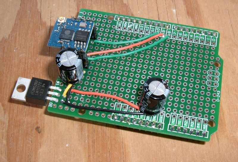
My wireless moisture sensor project, on paper, is reasonably simple. Some moisture sensors, an Arduino to read them, a solar panel, a charge controller, a power supply, and a wireless gizmo to talk to my network.
However, I’ve spent weeks trying to make the assembly work reliably. It would work on my desk, then fail in the project box. Or work in the project box and fail on my lawn. It was difficult to reproduce the problems, since they didn’t show up on the device side logs, and I couldn’t get much out of the device over serial - I was left troubleshooting from my access point (which, fortunately, has good logs). I finally determined that the problem was with the U.fl connector on these shields. I also found that some other ESP8266 modules had a nicer power control interface, so I built myself a shield from one of those and went on with the project.
Read on for lessons learned. May they help you avoid hours of wasted time.
External Antenna Modification
The SparkFun ESP8266 Wifi Shield includes a U.fl header for an external antenna. However, it’s not connected to the radio (the PCB antenna is). You need to move a bridge (0 ohm resistor) to connect the radio to the antenna connector.
Why would you want to do this? Outdoor connectivity would be a good reason - the PCB antenna isn’t amazing, and you want better range with a big panel antenna or something.
It’s not a hard process, but a fine tip iron helps. Heat the resistor up and rotate it to connect the U.fl path instead of the PCB antenna.
See the “000” resistor (jumper) dead center, connecting to the inverse F PCB antenna?

Rotate it 90 degrees. It’s kind of obvious what needs to happen, looking at it. If your 000 ohm resistor goes flying off into space, a bit of jumper wire should be fine. I’ve used both the provided resistor and a length of jumper wire with no discernible difference in behavior.

Once that’s done, you can hook up an external antenna for outdoor use.
However: I’ve spent about three weeks fighting this thing. Any time it’s set up for external antenna use, I have serious reliability issues. Most of the rest of the issues I’ve had seem to be entirely related to trying to use an external antenna (they go away with the onboard antenna), and I cannot, as of yet, make this shield work reliably with an external antenna.
I’ve tried a number of different antenna pigtails. Some of them work some of the time. Others are unreliable all the time. The internal antenna works perfectly, when it’s in range of the AP (not useful for, say, my lawn).
An easy test I’ve found is to get the shield connected to the AP, then floodping it (sudo ping -f [IP address]). If it’s working reliably, you should get all, or nearly all, the packets back. If you’re dropping packets on the external antenna and not the PCB antenna, welcome to my world. You’ll be fighting reliability endlessly, because it will work - some of the time. Just not all of the time.
Be warned. If you stick with the internal antenna, you should be fine. If you try to use the external antenna, here be dragons. And, if you do make it work reliably, please let me know what on earth you had to do! I’m hoping it’s just a bad batch of U.fl connectors, because this is a nice shield.
Deep Sleep & Wake
The only way to meet my power budget (a small solar panel is all the power the project gets, with a battery as a buffer) is to get both the Arduino and my wireless shield into a deep sleep state for the bulk of the time.
This leads to my other major complaint about this shield: It doesn’t expose the CHIP_EN/CH_PD pin to the user. According to the schematic, it’s tied to VCC with a pullup resistor, and that’s it. There’s no way to turn the chip off from this shield - you have to use the deep sleep mode. This is sad, because driving CH_PD low will power off the chip very nicely, and it’s a whole lot simpler than extending the libraries to support deep sleep.
Fortunately, there’s documentation about sleeping the ESP8266. Unfortunately, there’s a lot of staring at schematics and documents to work out what needs to happen. The good news is that the deep sleep functionality is easy, and the pins needed to wake the chip are exposed (which makes it easy to attach the required jumper).
Deep sleep mode on the ESP8266 is a quite deep sleep. It sets a counter, but otherwise shuts down. When it powers back on, it tries to connect to whatever is stored in the flash, and the calling code needs to wait for it to come up fully before talking to it - it won’t respond on serial before it’s connected and happy (though it will send status messages if you care to listen). If you’ve configured anything different from how it boots (the SparkFun library changes a few things), you’ll need to do that again when it wakes.
Hardware Modifications
The hardware modification for deep sleep is simple enough: connect XPD to RST. These pins are brought out in the ESP8266 GPIO section, so a simple jumper wire works well enough. The deep sleep mode sets a counter and then powers everything down. When the timer is finished, it toggles XPD. If you want the chip to wake up again, that signal has to make it’s way into the RST pin. So, solder a jumper wire from XPD to RST, and you’re set on the hardware side!

In theory, you could also wire RST to an Arduino GPIO pin with a 3.3v pullup. Ground the GPIO to drag RST low (output mode writing low), and tristate it (setting it to an input is close enough) to bring RST high. If you do this, you can probably wake the ESP8266 from the Arduino side, but you’ll still have to put it into a deep sleep, if you want the power savings.
Software Library
The SparkFun AT library is nice - but it doesn’t include the deep sleep command for some reason.
You’ll need to add that.
I added the following to the library, and it works as advertised. This is basic C++, so… if things don’t work after this, do your own learning.
SparkFunESP8266WiFi.h
In the “public:” section (I put mine in the “WiFi Functions” section):
bool deepSleep(unsigned long milliseconds);
SparkFunESP8266WiFi.cpp
Anywhere in the file (but, really, just put it at the end):
bool ESP8266Class::deepSleep(unsigned long milliseconds) {
  _serial->print("AT+GSLP=");
  _serial->print(milliseconds);
  _serial->print("\r\n");
  return readForResponses(RESPONSE_OK, RESPONSE_FAIL, WIFI_CONNECT_TIMEOUT);
}
This adds a “deepSleep” method that sends the serial command “AT+GSLP=[time]” - which will sleep for the specified number of milliseconds, give or take a few.
You MUST perform the hardware modification listed above, though! Otherwise, it will never wake up.
Actions on Wake
When the chip wakes up from deep sleep, it’s fully reset. Since the SparkFun library sets the SSID and security key in flash (by the use of legacy commands - the library really should be better about this), the chip will try to reconnect to the last AP, but you still need to call esp8266.begin() to reset some other parameters or things won’t work.
A good approach on wake (since the time to connect to the AP and get an IP varies) is to call esp8266.test() every second or so until it returns true - then the chip is up, connected, and you can call .begin() and go on your way.
Communication
Communication with the ESP8266 is simple enough with the suggested software serial, though there are a few helpful things to point out.
- It speaks using an AT command set. Here’s a handy reference.
- End every command with CRLF. Not CR, not LF. CRLF. ”\r\n” If you don’t send both, it won’t listen to you.
- If the device doesn’t get back to you in the command timeout interval, it’s probably busy. It doesn’t respond to serial commands if it’s busy. If you wait a few seconds and try again, it will probably work. No guarantees, but it’s going to work more often than not. If timing isn’t critical, sleep for 4s or 8s (conveniently doable with deep sleep code on the Arduino) and try again a few times before giving up. Sometimes the radio won’t recover, but if it doesn’t, you might have a power issue. See below.
Connectivity Issues & “Extensive Data Loss”
One of the hardest-to-troubleshoot problems with this card is when it simply doesn’t work. It’ll work on your desk, you deploy it into the field, and it doesn’t check in reliably or at all.
And, of course, any time you plug it in to debug it over serial, it behaves fine.
The next best option here is your router logs, if you have them. I run Mikrotik gear, which has very verbose logs, so I can see things like this in my log.
10:14:48 wireless,info 5C:CF:7F:XX:XX:XX@wlan1: connected
10:14:58 wireless,info 5C:CF:7F:XX:XX:XX@wlan1: disconnected, extensive data loss
10:15:02 wireless,info 5C:CF:7F:XX:XX:XX@wlan1: connected
10:15:11 wireless,info 5C:CF:7F:XX:XX:XX@wlan1: reassociating
10:15:11 wireless,info 5C:CF:7F:XX:XX:XX@wlan1: disconnected, ok
10:15:11 wireless,info 5C:CF:7F:XX:XX:XX@wlan1: connected
10:15:37 wireless,info 5C:CF:7F:XX:XX:XX@wlan1: reassociating
10:15:37 wireless,info 5C:CF:7F:XX:XX:XX@wlan1: disconnected, ok
10:15:37 wireless,info 5C:CF:7F:XX:XX:XX@wlan1: connected
10:15:44 wireless,info 5C:CF:7F:XX:XX:XX@wlan1: disconnected, extensive data loss
10:15:49 wireless,info 5C:CF:7F:XX:XX:XX@wlan1: connected
10:16:01 wireless,info 5C:CF:7F:XX:XX:XX@wlan1: reassociating
10:16:01 wireless,info 5C:CF:7F:XX:XX:XX@wlan1: disconnected, ok
This type of behavior, especially “extensive data loss,” means that the radio is having trouble staying connected - obviously. But, at least for me, “extensive data loss” was the clue.
I gained some minor improvement with power modifications (see below), but as near as I can tell, this all goes back to my issues with the U.fl connector. This never happened on the internal antenna, but I could reproduce it reliably enough with the external antenna - even in my office, a dozen or so feet from the AP.
Jammer Mode
During my development on this board, I ran into an interesting situation in which, on power on, the radio got stuck in a weird state where it started jamming my 2.4ghz connections. I don’t know what was going on, but I’d get the power LED, no STAT LED flashing, and whatever it was doing, it blew one of my 2.4ghz backhaul links right offline. This involved an hour and a half of troubleshooting (including half disassembling one of my radios) until I depowered the shield and everything went back to normal.
When it ended up into this mode, I was powering both the wifi shield and an I2C LCD from the Arduino’s 5v rail from a USB power source. I think this was a bit much. After removing the LCD, I stopped seeing this mode of operation. It seems to be an artifact of power starvation during startup. I really have no idea what was going on, though. Don’t do this. It needs a lot of power.
No, really. This board needs more power than you think it does.
Power Supply: Possibly Your Problem
If you’re having really weird issues with your ESP8266 - jamming the network or turning on but not trying to connect, or just generally being unreliable, there’s a possibility you have power problems.
This chip is well known for being somewhat abusive towards power supplies. It draws 50mA or so idle, bursting up to nearly 300mA when transmitting. The further away from the AP, the higher this will be.
And it does this with absolutely no warning. There’s no ramp or anything - just a serious hit to the power rails.
This shield is powered from the Arduino’s 5v rail by a fairly rapidly responding voltage regulator. However, if you have a questionable USB power supply (or a bunch of other hardware pulling power, like a LCD), it’s possible that your power supply isn’t keeping up.
You’re more likely to see this if you’re using a USB battery pack or something - a bit of research indicates that most of these units do not follow rapid transients quickly. They take a while to respond, because they’re designed for charging phones, not powering weird gizmos that abuse the power rails with sudden burst demands.
So, if your power supply can’t keep up, what’s one to do?
Improving Power Delivery
There are a variety of fixes for this. But I’ll share what I did. Did it help? Maybe. Maybe not. I’m certain it didn’t make anything worse.
I put a 470uF capacitor on the Arduino 5V rail. The ESP8266 is powered by a converter from the 5v rail, so I had two places to put a capacitor. The harder place is the 3.3V rail on the shield. This requires soldering. However, the 5V rail is easily accessible via the headers. So, I tried that first. Cut the pins to equal length, slide them in, and power things on. This is a quick and easy hack that will help stabilize your 5V rail. A standard capacitor will have 5mm pin spacing - so use the 5V socket and the second ground socket. It fits perfectly!
It helped, at least somewhat. I think.

Another option is to add a capacitor to the 3.3V rail. This requires soldering. Go from the 3.3V pin on the voltage regular to ground (pick a ground, any ground - they’re all the same).
Did this help? No, it didn’t. It might help you. But I wouldn’t bother with this again. This was an “I’m out of ideas, maybe?” type addition.

Final Thoughts
So: Given what I now know, is this a good WiFi shield or not?
If you want a nearly plug-and-play shield (you do have to solder headers) for indoor, short range use, and you don’t need to turn the chip off (or are willing to play with the jumper needed for deep sleep and some of the frustrations of waking it up): This shield is available at a good price for what it is. It brings out nearly everything on the ESP8266 (why they don’t bring out CH_PD is beyond me), and it’s a great little board for that purpose.
But I’m probably not going to use mine for much going forward. They’re a good bit more expensive than the ESP01/ESP02 shields on eBay, which come with the CH_PD pin, and even with a voltage regulator added, that route is cheaper. And works properly with a big external antenna. I’ll probably swap the jumper back to the internal antenna and give them to my daughter when she’s old enough to mess with things like this.
If the U.fl port worked reliably, I might have a different opinion. I’m certainly soured by spending a few weeks fighting this thing when my ESP02 module worked out of the box with an external antenna (and has been rock solid in my lawn for a week or so).
But if you’re not up for designing your own shield, you don’t care about power savings, you want something that just works (with the indoor antenna), and don’t mind putting headers on? Go for it!
If you are using one of these and it’s “floodping reliable” with an external antenna, please let me know in the comments. I really hope I just got a bad batch.
Comments
Comments are handled on my Discourse forum - you'll need to create an account there to post comments.If you've found this post useful, insightful, or informative, why not support me on Ko-fi? And if you'd like to be notified of new posts (I post every two weeks), you can follow my blog via email! Of course, if you like RSS, I support that too.


