
I have a daughter (not Cindy Lou Who, but she is slightly less than 2) who loves buttons and lights (“yight!”).
If something looks like a button, or looks like it could be a button, she’ll press it. Repeatedly - especially if it clicks! Clicking buttons are the best, and I’m glad things like dishwashers come with button locks now.
She’s also learning colors and letters. I had some time off over the winter, so I built her a button box that’s useful for all of these things!

This is the non-absurdly-technical description of my build. If you’re looking for the gory technical details with an awful lot of advice about how not to do things, you’ll want to check back next week for a radically longer post.
Otherwise, read on for how I built her button box!
Overall Design Concept
Some people would go into a project like this with CAD work, laser cutters, and micrometer precision. I went in with a pile of parts and a concept: “Button Box, with an LCD.” Most of the layout and design was done as I got to a particular point and worked out how things would fit, and some of it changed more than once throughout the project.
The LCD is important for word games longer term. The LEDs are important because colors are cool, and instant response to button pressing is useful.
And then, of course, buttons - because that’s the whole point! Lots of buttons!
LCD Display
I want this project to be useful for a while, and an LCD gives me a lot more options there.
The LCD I’m using is a reasonably standard unit - 20x4 characters, and I’m using one with an I2C backpack so I can control it with fewer pins.
This is for displaying status, letters, words, games… whatever I can come up with that’s appropriate for the stage of learning she’s going through. I won’t say the sky is the limit, but with 80 characters worth of space and 32k of program memory, I can have a lot of fun. There will be buttons below this screen to control it.

There is a proper tool for cutting openings, and the tool you have. I used a Black & Decker SkillSaw or whatever the proper term is - and… things got a little out of line, but, hey. Made by hand.

You’ll notice the opening is not exactly straight. That’s perfectly fine, since I cut the opening a bit on the small side anyway. I took a file and expanded it so the screen fits quite tightly into the space.

It fits! The back shows, first, that I did cram the LCD up as high as I could, and, second, the I2C adapter that lets me control this with just two data pins (technically, one clock pin and one data pin) from my Arduino. Actually driving the LCD takes 8 pins, but through the use of a handy, convenient adapter like this, and a library designed to work with it, I can control it with just two pins - which leaves more pins for things like buttons!

With things fitted, I checked functionality - yup! The screen works - though it does lie. It’s not, yet, a button box. It’s just an LCD screen, sticking through a project box lid.

Buttonholes and Lightports
The important part of a button box is the buttons - and, also, the LEDs that respond to the buttons. I sat down and came up with a grand plan for both of these: Drill holes. Insert buttons. Insert LEDs. Wire them, somehow. It’s a great plan! The best plan!
Drilling holes in something thin should start with pilot holes. I drilled small pilot holes for both the buttons and the LEDs, then enlarged them to fit the buttons. This enlargement process involved drill bits, hogging out the hole with the drill bit, a round file, and sandpaper. It could have, ideally, involved a drill press and the proper size drill bits, but I didn’t have those laying around.

After a bit of work, I had three buttonholes under the display, five buttonholes along the bottom, five lightholes above the buttonholes (for corresponding color LEDs - colors are important), and a bunch of holes in the center for wiring the LED strips.

BUTTONS! Where’s Mindy? Bad dog!

The buttons under the LCD are a different style - a bit more retro. The plan for them (which, I assure you, is a very rough plan) is to use them to control the LCD. In theory, I’ve got left, right, and a select button. In reality? Well, ask me once the software is done.

Wiring the Buttons
If you search the internet for how to wire up buttons to an Arduino, you get all sorts of stuff about pullup resistors, pulldown resistors, etc. They’re all missing the fact that the Arduino, internally, has these! It’s got internal pullup resistors on the pins! This means button wiring can be simple - a common ground for the buttons, and individual sense wires from each button to the input pins, with the pullup resistors enabled. If the button is not pressed, the pullup resistors do their thing, pull the voltage up to 5V, and you measure a logic 1 at the port. If the button is pressed, it overwhelms the pullup resistor, you measure a logic 0, and know that someone, somewhere, is pushing your buttons.
It’s really this simple.

The row of 5 buttons along the bottom is exactly the same - a common ground, with each button wired individually. More wire colors, perhaps, would have been nice here.

Wiring the 5 Colored LEDs
I have five buttons along the bottom - and five holes for colored jumbo LEDs. Conveniently, I have five different colors of jumbo LEDs that match the buttons (or, perhaps, I chose the buttons that match the LEDs - the world may never know!).
Before wiring things up into a final arrangement, I sat down with a breadboard to work out the details, and also to see if I could match brightness by playing with the dropping resistors. The blue and white LEDs, at full rated power, were simply blinding, and I’d rather not blind my kid. A bit of playing around with the resistors got something that was close enough to even brightness to go forward with.
The observant reader (or someone who has read the technical version of this post) might note that I’m using 60A MOSFETS (electronic switches) to switch LEDs that pull fractions of an amp. Yeah… the driver chips I had were all bad, and so I went with what I’ve got. Yes, I’m using 300A worth of switching hardware to switch, perhaps, 1/10th of an amp. Overkill is the best kind of kill!

With the circuit tested and the resistor values selected, I set about building something slightly more permanent. I have some prototype board that happens to fit the project box nicely, and the tolerances are loose enough that I can solder the LEDs into it and still have them fit in the holes.

A bit of soldering and wiring later, I have the finished LED driver board! The chip at the top is a shift register, and I use 5 of the 8 output pins to drive the MOSFETs, which switch the LEDs. Nothing terribly complex, though it is more than a little bit overkill. The various resistors work to get the LEDs to roughly the same brightness and to keep the voltage over each LED low enough to avoid burning them out. This board just slides in, the LEDs sit in their holes, and the magic happens with software!

LED Strips
The LED strips in the center are interesting little devices. They use some modern microcontroller driven RGB LEDs that are chainable and individually controllable - this means you can hook a ton of them together and still have full control over the brightness and color of each individual pixel.
They’re technically WS2812 LEDs, but AdaFruit refers to them as “NeoPixels” - just a nifty name for the same technology.
I have three strips of 8 I intend to use on my box. This is what they look like up close - and just in case you’re wondering, they get bright. I run these at 12% power and they’re more than enough.

They require power and ground wires, and do an interesting thing with signals where they propagate the signal through the LEDs - so you can connect the “DOUT” pin on one strip to the “DIN” pin of the next strip and treat everything as a single logical strip (of, in my case, 24 LEDs).

The six holes in the center are for these strips - the wiring passes through those holes and all the strips are looped together into a single 24 LED long logical strip to control. If I want to do something fancy with the three rows, I have to work out details myself.

After quite a bit more fiddling around with wire and learning some lessons about solid core wire for this (to be covered in greater detail in next week’s technical post), I got them all working nicely!

The strips are held down with my usual 3M adhesive strip (which I use for basically everything that involving sticking things together - if I’m not using hot glue). With the strips secured, the front panel is basically done - so 90% done, 90% to go…

Power & Wiring
The rest of the project consists of wiring everything up and getting it power. The technical writeup will go into far more detail, but I built myself an Arduino shield from a prototype board to handle power and signal delivery. The capacitors help filter power and smooth out any spikes caused by the LED strips cycling on and off.

This shield connects to all the front cover buttons - the wiring is a bit of a mess in there, but everything connects up, then I put the shield on an Arduino, add batteries, and I’m good to go!

A brief function test later, and everything works! At this point, the LCD is no longer lying!

Securing the LEDs
I took the box (running from a USB battery pack) for a toddler test - and determined that she was determined to test everything to see if it was a button. This included the LEDs and the LCD. The buttons are fine - they have surrounds that keep them from sliding back into the box.
The fix for both involved hot glue (my other preferred stick-things-together method). I simply let my hot glue gun warm up to the hot side of the operating range and squirted a bunch of hot glue in to hold the LEDs.


The LCD is secured similarly.
Battery & Charger
Finally, I built a battery pack for the box. I do lithium battery pack rebuilds for electric bikes, so I have a lot of these cells around - I just grabbed one of my many modules laying around.
There’s… oh, a lot of energy in these. I can run the toy for over 2 days straight on the energy in here. But it’s what I had convenient. Overkill is the best kind of kill!

The PCB I’m using for charging and 5V output is a random lithium battery based USB power supply and charger. I’ve used a bunch of these, and they work well enough. The big USB port on the left powers the gizmo, and the small micro USB port on the right charges - I’ll just run an extension cable to the outside for charging. The loose wire is for tracking battery voltage so I can tell if the box needs recharging.

Finally, the battery is crammed in a corner of the box after being wrapped to fit tightly, and the various power cables are wired up. I’ll be honest… this isn’t the tidiest setup I’ve ever worked with, and there’s no way I could ever take this on a commercial flight. However, it works!

Software
I can, literally, make this box do anything I dream within the constraints of the Arduino and the buttons/LEDs/LCD.
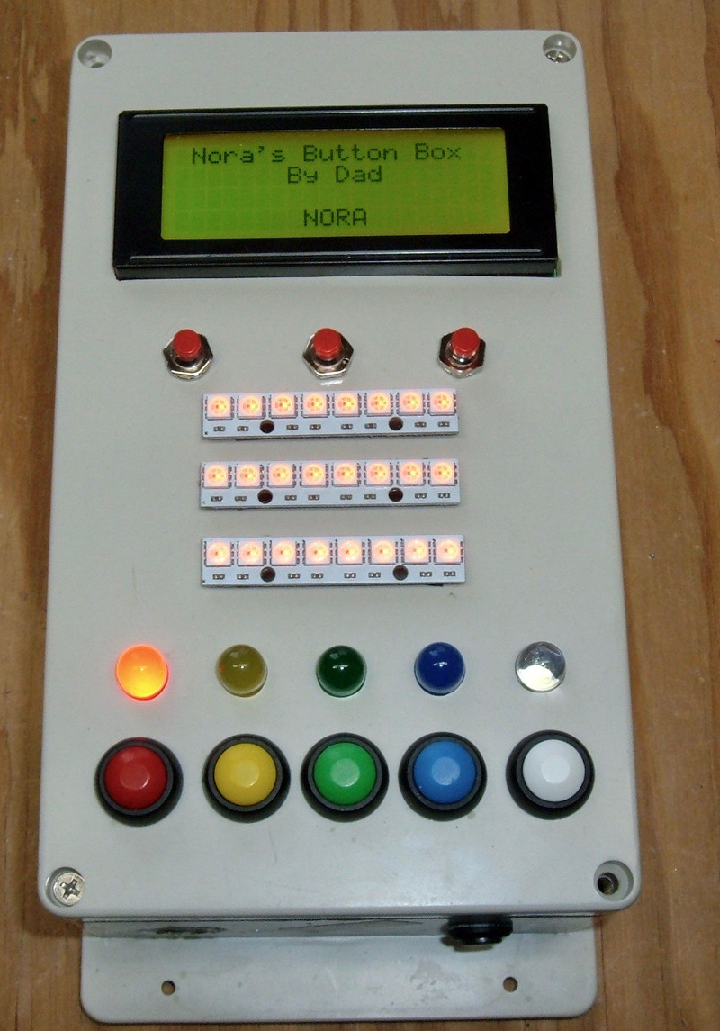
For now, the top buttons move the “NORA” back and forth, with the middle button centering it.
The bottom colored buttons turn on or off their corresponding LED, and change the center LEDs to match. If you turn on all the bottom LEDs, they all turn off.
Currently, the software is just polling button state - I intend to add interrupts at some point here, along with menu options for different ways of interacting with it.
Obviously I have a long way to go with the software, and it will evolve as she gets older - but the hardware is done and reasonably kidproof! And, most importantly, she likes playing with it!
Final Thoughts
Next week’s post will consist of much more detail for people who are interested in building something like this - and much of that will be “things I tried that didn’t work.” Or took longer than I expected. And a breakdown of components, cost, etc. At some point, I’ll talk about the software for it, but only after I make something fancier.
That said: if you’re moderately handy with small electronics and have kids, or know of kids - something like this is an awesome project. And, conveniently, as she gets older, she’s got an Arduino to play with that already has a wonderful set of input and output devices bolted on!
Comments
Comments are handled on my Discourse forum - you'll need to create an account there to post comments.If you've found this post useful, insightful, or informative, why not support me on Ko-fi? And if you'd like to be notified of new posts (I post every two weeks), you can follow my blog via email! Of course, if you like RSS, I support that too.


