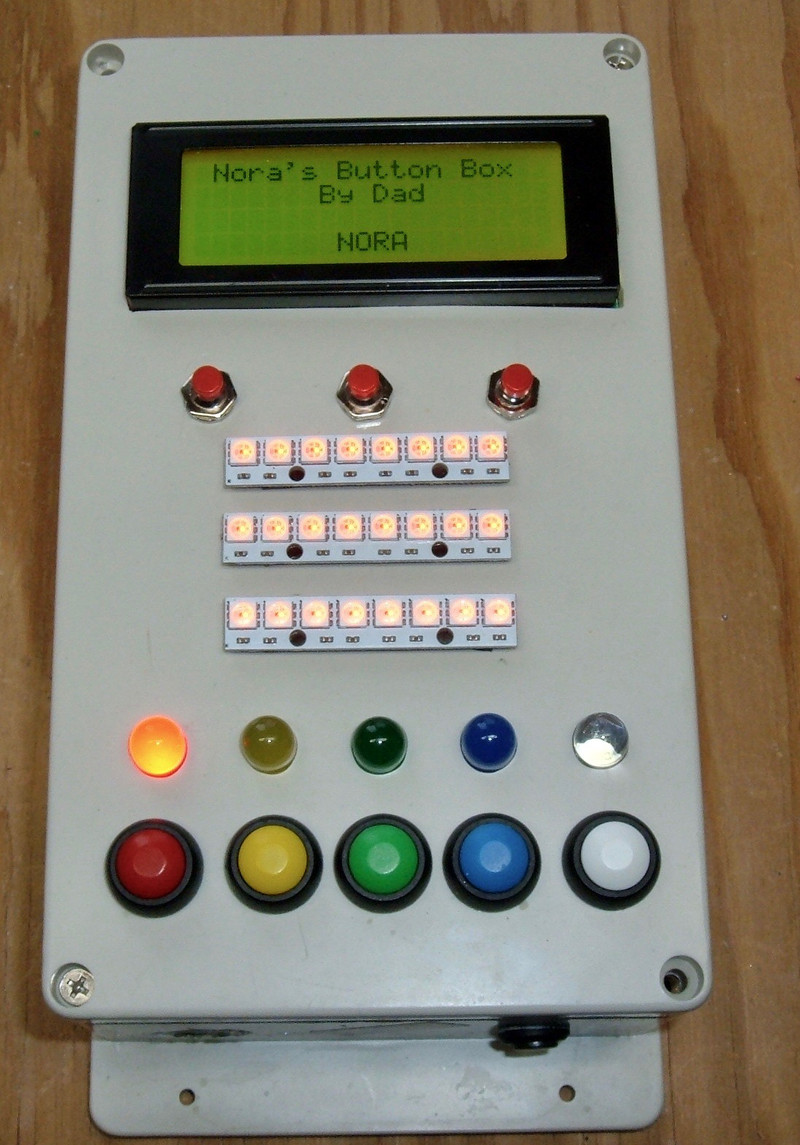

My daughter (23 months old) likes pressing buttons and anything involving lights (“yight!”). I had some time off this winter - and some parts to build something I call a “Button Box.” And what, realistically, is both a toy that can grow with her, and a subtle way to teach low level programming when she’s older (if she’s at all interested). Because nobody is learning C in schools anymore, and C still matters.
This box contains an Arduino Uno, a 20x4 LCD, a few NeoPixel strips, a bunch of buttons, some LEDs, a battery and power supply, and the supporting wiring mess to make it all work - entirely hand soldered, and certainly one of a kind!

I’m doing two posts on this. You’ve found the “highly technical discussion” post - this will be useful if you happen to want to build something similar, or find out what I did, in rather substantial detail. This post also includes lessons learned - places I wasted time, had to rework things, or would just do things differently if I were to do it again.
If you’re simply interested in what the build process looked like, you may be more interested in my other post, which is a (somewhat) shorter description of the build process. This post includes that content as well, so there’s no real point in reading both unless you want to.
In any case, if you want the gory technical details, read on!
Design Concept & Goals
I started this project with a pile of parts, a desire to build something I could call a “Button Box,” and a few days of free time between Christmas and New Years.
Past that, I pretty much designed as I built.
As I went through the parts I had, a few things solidified. One of my I2C LCD screens was going in - this opens up a lot of possibilities once she’s reading (so, at this rate, a few months). I wanted a way to navigate menus on the LCD (so a left/right/select button set would be nice). Beyond that, I wanted buttons, and LEDs, and blinking lights! And I had plenty of those to install.
Software-wise, my daughter isn’t even 2 yet, so I’m not in need of anything be particularly complex. I’ll work on the software as she gets older. But, for now, it’s more or less “proof of concept” software.
However, as she gets quite a few years older - this is an Arduino based system with plenty of inputs and outputs, so if she wants to hack on something, she’s more than welcome to hack on this. I may add a Bluetooth programming interface at some point just so I don’t have to open it up to program things - or I may build a Revision 2 in another year or two. I’ll just have to wait and see.
Case
The case for the whole project is a random waterproof project box I have laying around. I got these for another project that hasn’t been finished yet, but is responsible for an awful lot of posts here (some wireless moisture sensors).

This case falls firmly into the category of “I had it, it seemed like a good size, and there’s probably enough room inside to cram everything in.”
I played with the parts, and the initial test fit went well enough - the LCD mostly fit, I could fit a few buttons across, etc. So, really, this is a case of “What I have is good enough, and also is what I have.”
LCD (20x4 I2C)
The LCD at the top is a 20x4 character I2C LCD with backlight - easily available on eBay. If you’re spending more than about $5, shipped (from China), you’re either overpaying or very impatient. The nice thing about the I2C backpack is that you can run the LCD on two pins (SDA/SCL), instead of the normal 8 for an LCD of this type - great savings on precious pins for a project that needs a lot of pins. There’s just no reason not to use an I2C backpack for something like this.

The backside shows the I2C interface (the black PCB on the top of the LCD board) and the interface to the Arduino - +5V, ground, SDA, SCL. Note that SDA and SCL are shared with A4/A5 pins, so don’t use those for something else.

The pins from the I2C backpack stick out a good distance as assembled, so I trimmed them down. They’re not perfectly flat, but they’re a lot better than they were. If you want the LCD to fit tighter, you could take some sandpaper or a file to the pins and flatten them out, but be careful of the traces! I don’t care quite that much, so I’ve left them as-is, sticking up a bit. You’ll see that my tolerances on this project are loose, at best. You might even notice that the I2C backpack isn’t exactly level…

Fitting the LCD into the box lid involved seeing how far up I could place the panel while still clearing the lid with backplane board (the board being larger than the actual LCD), then marking the opening for it.

I initially thought I’d be smart with a drill and a hacksaw, but a quick survey of the size of the hacksaw, the depth of the gap between the blade and the handle, and the length of cuts needed indicated that I’d need another plan.

Said other plan was found laying around my tool cabinet! A good clamp and a good plastic blade would have been useful here. You can get away with less, but… eh. You’ll see.
In any case, pick a tool you have to cut the opening.

Unfortunately, the jigsaw got away from me a bit along the top - so… made by hand and all. This hole is deliberately cut a bit on the small side so I can file it to fit, but the top is up about as high as I can go (the board hits the project box tabs if I go any higher). Oh well.
I probably should have marked the flat surface instead of trying to cut from the underside, and just put some felt or something on the jigsaw feet to keep it from scraping up the lid.

I filed the opening to fit, and after a bit of time, my LCD pokes through, ready to go!

It sits almost flat, but not entirely (due to the pins sticking slightly out in the top right corner under the I2C backpack). However, you can see that the LCD board takes a good bit of the space in the lid. The huge open area around the LCD on the front is due to this interface board - I simply can’t put any hardware right around it.

The cable I’m using here is some security system 4 conductor cable I found at Home Depot - I use this for many of my projects. You can make a perfectly good plug in lead out of the end of a stranded wire with some solder. These ended up a bit thick - it works better if you have the wire slightly starved for solder (the red and black wires are better). But, they plug right in to the Arduino sockets!

With a bit more work, the LCD is installed, contrast is adjusted (seriously, contrast is a fiddly pain with these), and I have output! Yay!

Drilling Button & LED Holes
With the LCD installed and the no-drill zone around it figured out, I set about working out the details of LED and button holes.
A quick survey of the 10mm Jumbo LEDs I had and the buttons showed that I could fit a maximum of 5 across - any more, and I was starting to run the risk of them getting too close with not enough material to support them.
A sheet of graph paper cut to size makes a great guide for marking hole locations!

For drilling holes in plastic like this, start with a pilot hole, then enlarge.
I don’t have a set of metric drill bits, so I got close on the final size, then hogged the hole out with the drill and used a circular file to work out the final fit.
A drill press and the proper set of metric drill bits would be really, really useful here and save a lot of time.

By this point, I’d figured out what I was doing with the center LED strips, so I drilled wire holes for those as well - I’ll stick them on with my usual adhesive. I also drilled a set of holes for buttons up by the LCD to use for menu navigation.
The opening spacing and sizing isn’t perfect, but this adds character, or something along those lines! Mostly, I just didn’t realize how hard it was to get a good hole in a thin piece of plastic with a freehand drill. And I didn’t have a metric drill bit set. Serious, a drill press and a good set of metric bits would have shaved a few hours off the project of getting the holes drilled and fitted. On the other hand, everything is hand fitted…

Installing and Wiring the Buttons
All of my pushbuttons (with the exception of the power button on the bottom) are momentary pushbuttons, normally open. There are a wide variety of tutorials on how to wire buttons to an Arduino, but if you’re just wiring one button per digital (or analog - you can treat them as digital) pin, there’s a really, really easy way to do it: Have the button short a sense wire to ground.
If you configure a pin with mode INPUT_PULLUP, it enables an internal ~20kΩ pullup resistor on the pin. This means that if the pin isn’t connected to anything (button not being pressed), the pin will read as a high logic level. If you ground out the pin (say, with a button connected to ground on one side and the pin on the other), a button being pressed reads as a low logic level!
It’s inverted compared to how one might prefer things to work, but that’s just a quick software fix (which, I’d add, is cheaper than an external pullup resistor).
In any case, here’s what the wiring for the top three buttons looks like. You can see the common ground running across the top of the buttons, and the individual sense wires going out from each button. Those are normally kept high by the pullup resistors, unless the button is pressed, then that line is low. Simple!

The bottom buttons are wired up just the same. Common ground, individual sense wires.

At the other side of the sense wires, I’m using some standard 0.1” pin headers to plug into the Arduino. There’s probably a better solution here, but I didn’t have one at the time, so this is what I used.

The top buttons are an old style arcade pushbutton - rather clicky, all identical.

The bottom buttons are more colorful - and will correspond to the LED colors in the holes above them!

Wiring the Lower LEDs
The lower 5 LEDs are a set of 5 10mm LEDs that match the color of the button below them. I had a plan to drive these, discovered that a batch of driver ICs I had laying around appeared to be entirely composed of internally shorted junk, and ended up with something radically more overkill.
Instead of using one pin per LED, I decided to drive the LEDs through a SN74HC595 shift register. This lets me control up to 8 LEDs with 3 or 4 pins (I’m using 4 for now, which isn’t a huge gain over the 5 it would take me, but I can control more if I want, or other devices as well - think beepers). A shift register is a neat device that lets you push data in one end, and it ratchets through the device, eventually coming out the other end (if you care). It’s great to control a bunch of things on fairly few pins since they chain. With the same pin count, I could just as easily control 16 or 24 LEDs by chaining the shift registers together.
My shift register won’t drive a LED output (it’s rated at something like 6mA per output, and my LEDs take 20mA) - so I was going to use a SN754410 driver chip to drive them. These are motor controllers that should source around an amp, which would be fine for my needs.
Unfortunately, my whole batch of them seems to be quite shorted internally between the driver voltage input and ground. They get alarmingly hot in a hurry (touching things to find what smells like hot IC is a remarkably bad idea if you don’t like burned fingers), and are drawing something like 1.5A through them - with everything disabled. So… I have no idea what’s wrong here, but they simply didn’t work. I got about this far - the left chip is a standalone chip instrumented with an ammeter on the input side, with which I discovered why it was getting so hot. 7.5W being dissipated in that chip is too much. And, more importantly, means something is just majorly wrong with it. All of mine are bad. The joys of eBay… Test things when you get them instead of months later.
This makes a solid argument for a good resistor on the input side of something that isn’t supposed to draw much current, by the way. A resistor is a cheap enough thing to fry, and if you’re expecting milliamps of input and see amps, a decent resistor will just drop the voltage enough to not cook things.

Looking around for other hardware to switch power with, I realized that I have a drawer full of NPN power MOSFETs (IRLB8721s, if you care). These are rated for somewhere around 60A each (with proper heatsinking). Anyway, I have them, and they work.
I decided to breadboard the LEDs first, before soldering anything up, because I wasn’t sure about the brightness of the various LEDs. I can always PWM the output, but it’s much easier if the LEDs are roughly the same brightness to start with.
I fiddled around with resistors quite a bit before settling on something that, visually, looked pretty close. The green is slightly dimmer than the others, but it’s running at maximum current/voltage. The white one, I pulled back quite significantly. It was blinding with the full power to it, and is still pretty bright at radically reduced voltage. Blue is cut back a good bit as well.
But things work! I can switch the LEDs and have them all on from my shift register. I… also have enough MOSFET here to switch about 300A. For a total load of slightly north of 100mA. But what’s a factor of 3000 among friends?

In any case, with something that works, I set about transferring this to a prototype board I had laying around.
Funny story about this type of perforated copper proto board: Back in high school, a friend and I decided to do something fun with the old disposable cameras you could get (in the late 90s, film was a thing, disposable cameras were an admittedly absurd thing, and if you asked nicely, you could usually get a shopping bag full of them for free from any drug store photo department - complete with AA battery). Those cameras, while empty of film, still had a huge capacitor, a charging setup, and a flash. Which, by the way, can be made into a great hat, assuming you don’t mind the risk of setting your head on fire if it rains during a particular marching band practice.
Anyway, being not particularly well educated in the fine details of current, resistance, power dissipation, and such things, we decided to solder a bunch of camera capacitors onto a board that looked an awful lot like this one to make a huge parallel capacitor for zapping things. The charging went fine, but when we went to go zap something, there was a huge bang - from the proto board. A bit of poking around with a screwdriver (high schoolers, not particularly smart about the electrons) indicated that all the other capacitors were still amazingly well charged. Further inspection indicated that we’d blown several traces completely off the proto board, and some of the others had been well on their way to being vaporized. Copper isn’t a superconductor!
Back on topic, some test fitting demonstrated that I could actually hook the board directly to the LEDs, as they sat in their holes, and get things close enough to fit!

A nice perk about boards like this is that you have the fingers running back and forth, which are designed to be used as a power and ground bus. For this setup, I’m switching on the ground side, so the LED anodes are soldered straight to the positive bus (I declare that one positive, because I’m building it, and I can do that type of thing), and trimmed shortly after the solder joint.
If you’re doing this, use a bit more solder than you think you need. My joints started out solid electrically, but weak mechanically, and I had to add solder to a few after moving things around. A structural solder joint is larger than an electrical solder joint.
This isn’t the prettiest soldering job I’ve ever done. It only gets worse from here, but it does work!

Flipping the board over, I’ve got the MOSFETs - IRLB8721s. The cathode (negative terminal) of the LEDs is connected to the resistors, which go into the center pin of the MOSFETs. The right pin goes to ground. And the left pin is the control input.

I’ve flipped the board over here, keeping the right/left alignment. You can see, perhaps, through the mess of solder and reflections that the resistors are connected to the LEDs with the top pad (two pins), and come down to join the MOSFETs in the center. The right legs of the MOSFETs are bent back and connect to the other bus bar, which is reasonably enough the negative side of things.
Again, this isn’t pretty, but it’s quick, it’s easy, it works, and it’s totally fine for a one-off project like this. I have no interest in fabbing PCBs for it.

Ok, that’s a lie. I would fab a PCB for it, but I don’t want to take the time, and I don’t need a whole bunch of identical PCBs for one button box.
The shift register is up at the top and wired with a spaghetti of wires to drive the MOSFETs. I’m using one of my four conductor security system wires to carry the signals from the Arduino, and green signal wires, because green is… for signals. Or something.
This is an acceptable place to use solid core wire. The rest of the project where I use solid core? Don’t. It’s more trouble than it’s worth. Get some stranded wire and save yourself the trouble of cracked solder joints. The solid core stuff just doesn’t work well.

The backside shows the completed ~hack~ wiring job. It’s fun with bent pins and solder bridges, but they’re on purpose! I’d say it doesn’t look this ugly in person, but it actually does. Lots of residue, and not the cleanest joints. This is the first time I’ve worked with proto board like this in a long, long time, and it shows.

But, it works! I swapped the connections from my breadboard over to the unit going in the Button Box, and it works exactly as advertised. Woohoo!

Center LEDs (NeoPixel/WS2812 RGB LEDs)
The center bank of LEDs consists of three strips of 8 RGB LEDs. These are individually addressable LEDs with a rather bizarre timing based communication protocol, but there are some nice libraries out there to work with them. You can control the 8 bit R, G, and B channels of each one separately, and they are bright. I throttle them back substantially to avoid blinding people (fully on for this box is 32, out of a max of 255).

The interface on the back is pretty simple, and supports chaining. Top and bottom pins are ground. The LEDs require 4-7VDC, though I just feed them the same 5V as everything else. On the left, there’s a DIN pin - this is the input data signal. The signal is boosted by each LED’s driver circuitry and propagates through the chain, coming out on the DOUT pin - which you can then hook into the next strip. This allows, in theory, infinite LEDs controlled with one data wire. Realistically… well, you can still control more LEDs than you reasonably can use with one data wire!

Adafruit has a pretty neat NeoPixel library - you can either install it from inside the Arduino IDE by searching for “Adafruit NeoPixel by Adafruit” in the Library Manager, or you can download the latest version from their GitHub link (above) and install it in the normal manner.
My first attempt to wire these up involved stranded four conductor wire. This would have been a good option to stick with.

However, I couldn’t get the wires sitting quite as flat as I wanted, so I replaced that with some solid core wire I have. This turns out to be a bad idea! I had to resolder several of the connections after the LED strips were installed, because the solid core wire transmitted too much force and broke the connections. You can reheat and reflow the connections from the side, but simply going with stranded wire would have been a far better option, it turns out. I could have just pulled wire out of the external shield and been fine. Lessons learned.
This is also another place where using a bit more solder would have been a good idea.

However, even with the solid core wire, the strips work. Top strip, sitting in place for a test.

I’d initially planned to control all three strips separately, but realized that I could save some pins and make my life easier if I looped each strip’s DOUT to DIN on the next strip. I only did this for the signal - each strip is powered from my main power shield separately. Realistically, with how few amps I’m pulling on this, I could have chained them, but the wiring is about the same either way.

They work! I just used a spare breadboard to power them while testing everything.

Power and ground wires from the strips are joined together in 0.1” pin headers, just like everything else.
Advice: If you’re doing something like this, after soldering the wires to the pins, wrap the wires and pins with some sort of thin wire and just solder bridge the whole thing up. They’re all going to the same rail, and you’ll save a lot of time of tracing down why one of the strips is acting up (because the power lead is loose under the tape). And use stranded wire.

The strips are, as is usual for me, secured to the front cover with 3M double sided trim adhesive. I needed two layers of it to clear the wires, but they fit!
With everything on the front panel done, I’m at about the “90% done, 90% to go!” point.

Power Shield
I usually power my Arduino projects from the first shield layer - you can happily power an Arduino by putting 5V on the 5V rail, skip the USB plug entirely, and eliminate a few things from your power supply. You also eliminate over-current protection, but since anything drawing power gets power from the shield, I’m not too concerned.
My power shield is a bog standard Arduino prototype shield, with pins soldered on the edges.
I’ve got 2000uF worth of 10V filter capacitors between 5V and ground to help smooth any sort of transients. It doesn’t hurt, 1000uF capacitors are cheap, and it’ll often prevent weird glitches down the road.
The short row of sockets is +5V, the longer row is ground (the LED strips have two grounds), and the filter capacitors are on the end! The two wires coming in go to my power supply.

If you have pins coming out the bottom, you can just bend them and solder them to get your very own high current bus! It’s not the first time I’ve done this and it won’t be the last. Is it ugly? Kind of. Does it work? Absolutely! Is it crazy overkill for less than half an amp? Yes!
The solder glob at the bottom left corner ties the two ground pins together - the Arduino has two ground pins over there, and I may as well tie them together on my shield.

With everything hooked up, there are a lot of wires going places, but they all do things.
The top right corner wires (green and white) are the I2C clock and data lines to the LCD. The four pins below that (D10-D13) go to the shift register to control the single color LEDs. D6 goes to control the three LED strips in the middle. The bottom set of 5 connections (D2-D6) goes to the color buttons, and the set of three over on the analog side goes to the buttons below the LCD. They’re not in the right sockets here - they should be in A0-A2, but I keep forgetting that they’re reversed over on that side.

So far, everything is fitting. The wires hanging down connect via a USB A plug to the converter on the battery, and are run through the switch in the lower left corner of the case to turn the whole thing on and off.

With power run, I ran a USB cable into the box to power things before I got the battery wired up and banged out a quick firmware to play with - the buttons light the corresponding LED and turn the center LEDs that color.

Securing the LEDs & LCD
A brief evening test of “Button Box vs Toddler” demonstrated that said toddler presses everything, including the LCD and the LEDs. Which… weren’t properly secured.
I fixed that with some hot glue. Hot glue, a hot glue gun that’s on the warm side of its operating range, and you can secure just about anything to anything!


The LCD is similarly secured with about a stick worth of hot glue around the edges, and isn’t going anywhere.
Power Supply & Battery
Single lithium cell USB power supplies and chargers are cheap and easy to find. I’ve got a few of them laying around, but I wasn’t sure if any particular one was good or not (I’ve… perhaps damaged one or two of mine, in “testing”). Fortunately, I’ve got all the equipment to test such devices! The power supply is on the left. One of my (many) USB voltage/current meters is in the center - and an adjustable USB load bank is on the right. The button box pulls about 0.2A at 5V when running brightly, and this one is holding voltage at almost 0.8A, so, good enough! Yes, I have all this stuff. Yes, I’m weird. Yes, it’s useful.
I went with this particular power supply board because both the charge port and the output port are on the same side. This is convenient for how I want to lay things out.

The actual battery I’m using is just a random pre-built module I had laying around for ebike battery builds. It’s a 13.5Ah, 3.7V module, for right around 50Wh. A set of three AA batteries has somewhere around 7.5Wh. Overkill? Certainly. I calculated I can run the Button Box for over 2 days continuously with this battery. If you do the math, you’ll find that each cell is 2250mAh. This is low for modern 18650s, but it’s the best I can find for the Sony US18650V series of cells, which is a spinel LiMn chemistry that exhibits a minor self-balancing behavior and is well suited to BionX battery pack rebuilds.

One little feature I like to add to my builds is the ability for the Arduino to sense and report battery voltage. This requires an inline resistor, or the Arduino will attempt to run on power from the analog in pins. I’m pretty sure this isn’t doing anything any favors.

My tested-and-good power supply is attached to the battery. The USB A port provides power to the rest of the system at 5V, and the micro USB port on the right is for charging.
Charging this pack takes a while - it charges at around 1A, which means it takes around 15h to recharge fully. Oh well. Not a problem.

The battery is wrapped with a few more layers so it fits snugly in the corner of the box - it’s easy to remove, but it won’t come loose without some work. I don’t want to glue it in place, but I don’t want it sliding around.

The charge connector is a micro USB extension cable that’s run through a hole in the bottom of the box and then hot glued into place. I was planning for it to be level, but… anyway. It’s there.
I don’t have a way right now to program the board remotely - I have to pull the top off to connect. I’ll eventually either add a programming port or a bluetooth interface for wireless programming.

Finally, with all the pieces in place, I can close the lid and screw everything together!

And I have a button box!
Software
Right now, the software isn’t terribly fancy. The lower buttons control their respective LEDs, and turn the center strips that color. The top buttons slide her name back and forth.
However, there’s a lot I can do with this. I have full control over the entire box!
One useful feature on the AVR chips to be aware of is that you can set an interrupt on pin state changing - not just the normal external interrupts. So, if I want, I can have an interrupt to deal with button state changes. Right now, I’m just polling, because I’m lazy.
I’ve got 32kb of program memory to play with, and not much in the way of SRAM use, so there are a lot of possibilities here.
Parts List
If you want to build something more or less identical to what I built, here’s a list of parts you’ll need. I’m not including some of the generic parts like wire and assorted resistors, because I assume you have your own supply of things like that. You can find parts both on eBay and Amazon, though eBay usually has better prices, especially if you’re willing to wait for international shipping. One-offs are more expensive than bulk, obviously, so I’m using something closer to bulk pricing - I usually don’t order 1 of something, I order 5, or 50, because the cost is better and then I have items for future use.
Project Box (200mm x 120mm x 75mm): $8 (eBay) (Amazon)
Arduino Uno: $3-$25, depending on your clone tolerance (eBay) (Amazon)
Arduino Prototype Shield: $2 (eBay) (Amazon)
10mm LEDs (red, green, blue, yellow, white): $7 for a lot (eBay) (Amazon)
12mm Colored Buttons: $2 (eBay) (Amazon)
7mm Red Pushbottons: $2 (eBay) (Amazon)
I2C 20x4 LCD: $5 (eBay) (Amazon)
8 Pixel WS2812 Strips: $2 (eBay) (Amazon)
Proto Board: $3 (eBay) (Amazon)
NPN MOSFETs (IRLB8721): $2 (eBay) (Amazon)
Shift Register (74HC595): $0.25 (eBay) (Amazon)
Power Pushbutton: $0.25 (eBay) (Amazon)
USB Charger and Power Supply: $3 (eBay) (Amazon)
Lithium Batteries (find your own locally): $4?
Micro USB Extension Cable: $2 (eBay) (Amazon)
And, as far as my cost? I really have no idea, nor do I care. I have a lot of the parts just laying around from bulk orders, so I’m paying a lot less per item for many of these than you might for a one-off. I expect it’s $30 or so in parts, and maybe 12 hours of work? If you do it, hopefully you can be more efficient with my tips.
Lessons Learned & Things I’d Do Differently
There are a number of things I’d do differently, with what I know now, if I were to do this again. Hopefully they help you, if you decide to build something similar!
Use Ribbon Cable
A lot of the issues I had would have been radically reduced, if not eliminated entirely, if I’d used some stranded ribbon cable for the various connections internally. It would be a lot easier to hook up, and make things neater.
Don’t Use Solid Core Wire
I fought the solid core wire endlessly. It kept popping solder joints loose as I was moving things around. It popped off the header pins, it popped off the LED boards (two different connections), and just generally was a pain. So if you don’t want to use ribbon cable, at least use stranded wire.
Get Some Sort of LED Panel
The three strips of 8 LEDs in the center are fine, but I’d have been better off with a LED panel crammed in there. You can find 4x4 panels, 4x8 panels, 8x8 panels… any of those would have made for a nicer looking and denser center section, and would have been easier to wire up.
Use Proper Drill Bits & a Drill Press
Get a 10mm drill bit for your 10mm LEDs. And use a drill press - that way you drill round holes, not the goofy-shaped holes you get with a portable drill in thin material. You can do it without, but it would have saved a few hours to have the right tools there.
Final Thoughts
So far, she loves playing with it. It’s a neat little box of lights, and as she grows, I can update the firmware on it - and, later on, she can update the firmware by herself!
I’m thinking about running a programming port out at some point. That wouldn’t be terribly difficult, and would make the unit it nicer to work with.
But, if this looks like a fun project - absolutely, go for it! It’s the type of thing where rough around the edges is perfectly fine, because it’s a custom one-off build for your kid.
If you build one - let me know below, in the comments. And if you really, really want something like this but don’t want to build it from scratch, let me know as well. If there’s enough interest, I might put a kit together with some PCBs.
Comments
Comments are handled on my Discourse forum - you'll need to create an account there to post comments.If you've found this post useful, insightful, or informative, why not support me on Ko-fi? And if you'd like to be notified of new posts (I post every two weeks), you can follow my blog via email! Of course, if you like RSS, I support that too.


