
If you need a basic LCD display for an Arduino or Raspberry Pi, it’s hard to beat these I2C LCD kits you can find for about $5 on eBay.

Some of them come soldered, some require you to solder things together - but they’re cheap, they’re I2C, they work… and they are incredibly frustrating when you didn’t write down the magic incantation to initialize the LiquidCrystal_I2C class, and cannot manage to get the silly things working again!
Fear not! With a bit of time, a bit of knowledge, and a cheap multimeter, you can figure out exactly how to set one of these up, starting with nothing but the adapter module!
Read on, if this particularly arcane corner of tech interests you. But you’re probably here from a search engine…
Assembling I2C LCDs
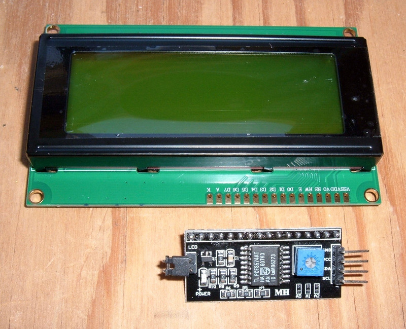
If you’re buying these on eBay and going with the cheap vendors, you get two pieces - the LCD assembly, and the I2C adapter. It should be obvious which is which. If you buy the few-cents-more version, they often come pre-soldered.
Assembly is pretty straightforward. Put the I2C adapter on the backside of the LCD board. It can go two ways, so put it the most reasonable looking way - board facing in. It won’t work the other way.

Then solder the pins. A small alligator clip or similar is useful to help keep the interface board fully pressed against the LCD board while soldering.
You’ll note I was lazy here and just soldered my interface wire to the input pins. It works fine…
Importantly, the blue potentiometer controls contrast. If you can’t see anything at all, fiddle with this!
If you’re working with random 4 conductor wire like I am, the conductors are almost certainly multi-strand. A bit of solder turns them into solid pins you can insert into, say, Arduino sockets!

These boards are all using a HD44780U or compatible controller - the datasheet is a fun read, but not entirely relevant for using them. If you want to do something beyond just displaying text, the character bitmaps are useful to know about.
Cheap LCDs and Their Pins
The LCDs have quite a few pins - and most of the matter! Here’s a rundown of the pins and what they do. You will probably have something along these lines.

Vss: Ground/0V.
Vdd: +5V
V0: Contrast.
RS: Register Select
RW: Read/Write
E: Enable
D0-D7: Data pins. Be aware that the normal wiring is to use 4 data pins, which are D4-D7, as opposed to the more reasonable seeming D0-D3.
A: Backlight +
K: Backlight -
Notice that both ends are ground, and the next pin in should be Vcc. This means that if you put your board on backwards, it’ll still light up the backlight - but the panel won’t actually work.
I2C Adapter Boards
The common I2C adapter boards you find for this purpose will look something quite a bit like this.
Four pins on the end for the power and I2C, a whole row of pins on the top, a potentiometer to set contrast, possibly a jumper for enabling the backlight, and a fancy chip in the center.

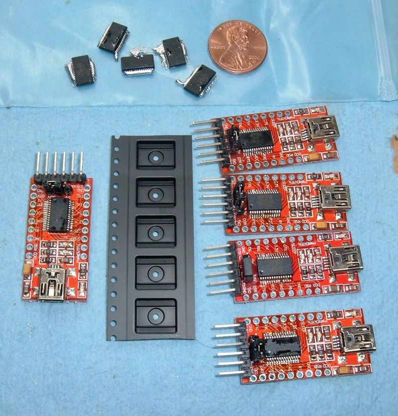
What’s that chip?
It’s almost certainly a PCF8574 of some variety.
This is a simple chip that sits on an I2C bus, reads bytes, and puts the bits of the byte out on 8 data pins. Several different manufacturers make them, but the NXP datasheet and TI datasheet should cover your needs. What matters most is the pinout for your chip.


The interface boards simply take a byte as an I2C slave device and write that byte onto the parallel output bus - which, conveniently, has just enough pins to run the LCD (if you happen to be using 4 data pins instead of all 8)!
This would be easy if everyone wired the chip to the output pins the same way. But, of course, they don’t - so you have to know how your particular adapter is wired up. If you can find the data from the seller, great - but a lot of them don’t include the details (or you’ve forgotten which vendor you purchased a particular board from). This isn’t a problem - I’ll teach you how to work out the details and get things working with nothing but the board!
Scanning for I2C Devices
The first thing you’ll need to know is what I2C address your board is using - otherwise, you’re just sending commands out into the void, and nothing will work.
You could look up the particular chip you have, find the data sheet, and puzzle it out that way, or you could just scan for it.
There’s a particularly handy I2cScanner sketch sitting over on the Arduino playground. This is exactly what you need. Wire things up, toss the scanner script into a sketch, upload it, and if everything is working, you’ll get something like this:
I2C Scanner
Scanning...
I2C device found at address 0x3F  !
If the adapter is the only device attached, which it should be if you’re looking for it, this is your address - 0x3F for my adapter.
If you don’t find anything here, ensure that things are wired properly - and if that doesn’t fix it, it’s worth putting a pullup resistor on both of the I2C lines (SDA and SCL). The Arduino internal pullup resistors work (barely) for very short I2C busses, but they’re way too high a resistance for crisp bus behavior, or even a bus beyond a few inches. Try a 4700 ohm resistor or so - it won’t hurt, and it often resolves I2C issues.
Once you have the device located by I2C address, it’s time to go on and figure out the pinout.
Buzzing Out Boards
For the next step, you’ll need a multimeter. It’s radically easier to do this if your multimeter has a continuity check tone - and also gives name to the technique, “buzzing out a board.”
The goal here is to find out which data pin from the PCF8574 connects to which LCD input. This information is needed to configure the LiquidCrystal class to drive your panel.
There are 8 outputs, and 8 pins of interest. So, get your multimeter set up and let’s go!

It’s a good idea to play around with some pins you know first - ground, or Vcc. There can be flux residue or a conformal coating over the board, and that can make it hard to get contact. On my board, I had to touch the actual leads coming off the IC, as I couldn’t make reliable contact with the solder holding it to the board.
But, once you figure out what works for making contact, go through and map the pins of interest from the output pins of the board to the leads on the IC they correspond to.
You’ll need to find RS, RW, E, D4, D5, D6, D7, and the backlight control pin.
This is what I was able to buzz out on my board. The backlight pin isn’t connected straight through (there’s a transistor in the way), but the process of elimination makes it pretty clear where the backlight control is!

You’ll probably find that D4-D7 correspond to either P0-P3, or P4-P7 - it just depends on the board. The wiring for the rest? Well, that’s why you’re here!
Initializing New Liquid Crystal
To work with an I2C LCD from an Arduino, you probably want to use New Liquid Crystal - the stock library doesn’t work with I2C adapters, and it’s not trivial to drive a display like this over an I2C adapter.
There are a number of ways to initialize the library, but if you’re this far, it’s probably because the simpler ways (with defaults) don’t work. You can take a look at the ways to initialize things in LiquidCrystal_I2C.h, but the most verbose method is the following:
LiquidCrystal_I2C(uint8_t lcd_Addr, uint8_t En, uint8_t Rw, uint8_t Rs,
                  uint8_t d4, uint8_t d5, uint8_t d6, uint8_t d7,
                  uint8_t backlighPin, t_backlighPol pol);
This constructor lets you specify everything needed to make the I2C expander work.
lcd_Addr is the I2C address of the expander (found with your scanner above), most of the values are the bit number of the output from the expander (bits 0-7), and the last argument is the backlight polarity.
Given the data from the last two steps, the incantation to initialize my particular board is this:
LiquidCrystal_I2C lcd(0x3f, 2, 1, 0, 4, 5, 6, 7, 3, POSITIVE);
The address (0x3f) comes first, then the output for the E pin (2), RW pin (1), etc. Look up at the diagram I made and it should be clear.
Backlight polarity is just one of those things you have to try. If the backlight does the opposite of what you command, change it from POSITIVE to NEGATIVE, and try again.
If you got it right, you should be able to output something to your LCD!

Contrast Adjustment
If you can’t see any text, and you can’t see the faint background squares - play with the contrast adjustment! I’m ashamed to admit how long I spent messing around before figuring out that I was writing things perfectly well, but had the contrast set entirely wrong.
Here’s what the display looks like with the contrast set wrong - absolutely blank, other than the backlight. You can write to this all day long and not see a thing.

Fiddle with the contrast until you can see the faint outlines of the character squares. Then try to write something to the display.

If you haven’t initialized the LCD at all (there’s voltage present, but the LiquidCrystal class hasn’t started up yet), you should see alternating rows of dark and light squares. This is helpful to verify that you have your contrast set at least somewhat sanely. If you don’t see this, play with the contrast first, or you’ll drive yourself batty trying to figure out why your screen isn’t working, when it’s working fine!

Final Thoughts
It would be nice if the various manufacturers would come up with a standard and hold to it - but evidence shows that won’t happen, so the next best thing is learning how to figure it out without a reference.
It might be worth buying a bunch of adapters at once, so you don’t have to figure out which pinout you’re dealing with. Or just make notes and keep track of the different adapters.
In any case, not knowing the pinout just isn’t that big a deal. A bit of time with a multimeter, and you’re on your way!
If this has been helpful, let me know below in the comments.
Comments
Comments are handled on my Discourse forum - you'll need to create an account there to post comments.If you've found this post useful, insightful, or informative, why not support me on Ko-fi? And if you'd like to be notified of new posts (I post every two weeks), you can follow my blog via email! Of course, if you like RSS, I support that too.


