
The FTDI FT232R chips are an incredibly well supported and common way of building USB to serial adapters (usually 3.3V or 5V TTL levels). The chips have built in drivers on all major OSes, they’re easy to find - and almost all the cheap ones adapters there are using fake chips.
But, with a bit of time and patience, you can replace the fake FTDI chips with legitimate ones! If you like the form factor of your preferred cheap adapter, but need the performance of a real FTDI chip, it’s quick and easy to swap them out!
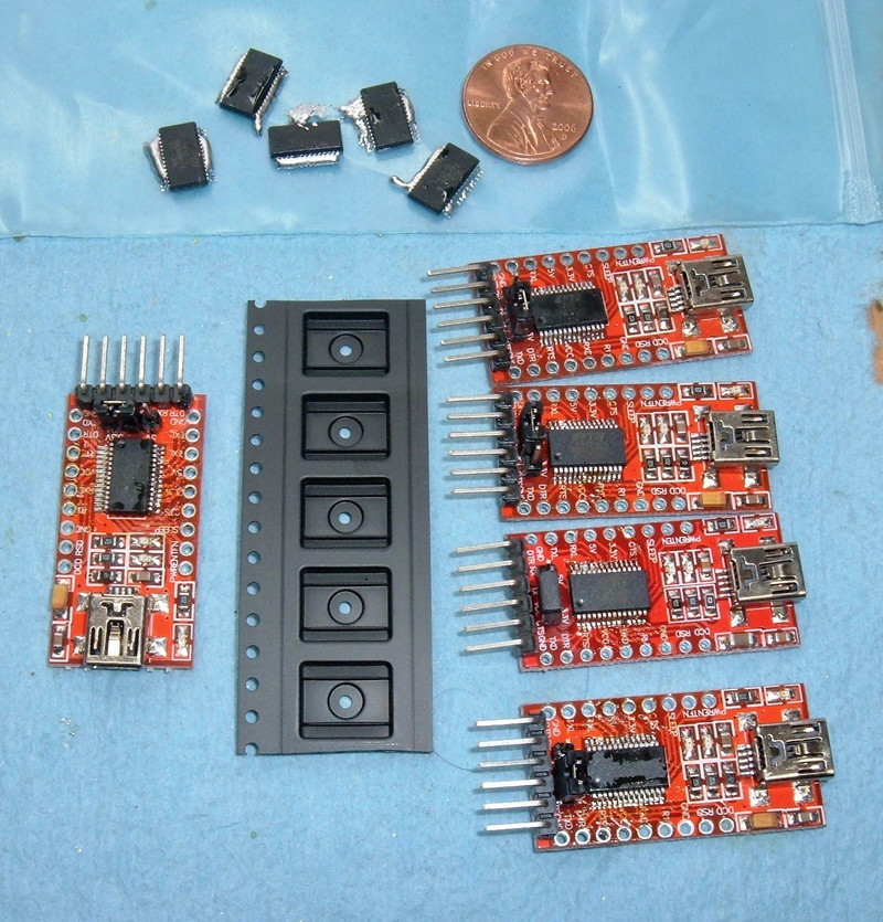
My first attempt (on the left) failed, but I then knocked out 4 functional replacements (on the right).

I’m talking about these adapters - you can find them for about $2, shipped, on eBay.

The chips aren’t fake in the “Oh, the factory ran an extra few shifts off the books” sense. They’re fake in the “The fake chips are actually a microcontroller programmed to behave (almost) exactly like the FT232R” sense - and, they do a pretty good job at low speeds!
Zeptobars did some analysis and demonstrated that the fake chips are completely different under the hood, and then of course FTDI messed with their drivers to either brick the fake chips or insert garbage data if you’re using one on Windows.
I have a bunch of these adapters laying around (purchased before I realized just how common the fake chips were), and while they work just fine at 115200 baud, they don’t work reliably at 3M baud. I spent a while troubleshooting some connections - things just weren’t working right and an awful lot of garbage was coming across my link. I eventually discovered the problem with fakes, and set out to both fix my problem and learn some surface mount rework skills.
So read on!
Fake FT232R Identification
FT232R chips have a unique ID burned into them - at least, the legitimate ones do. The fakes have an ID, but it’s hardly unique - the same ID will be reused extensively before a new ROM is spun. This makes identifying the fakes easy - buy a few, and if they all have the same name, they’re fake!
On OS X, a dead giveaway that you’re dealing with fakes is that you end up with weird names - they should be named by the serial #, and if there are duplicates, you’ll end up with weird names like this.

Another way is to search for your chip’s serial number. A50285BI is a common fake one, and if you see any hits for your serial number on Google, it’s almost certainly a fake.
Or you can look at cost. In bulk, on Digikey, the legitmate FT232RL chips are about $2.85 (at the time of posting). Did you pay less than that for an adapter? The chip is almost certainly fake! And if it came from China, it’s almost certainly fake.
There are plenty of resources to identify fake chips, but I’ll assume you have one of the adapters I listed above (or something similar) and would like to resolve your problems properly.
Surface Mount Rework
I set out to replace my fake chips with legitimate chips. I wanted reliable 3M baud communication, and also hands on experience with surface mount rework (I’ve not done it before). Since the adapters are cheap and the legitimate chips are cheap-ish ($4.50/ea in small quantities), it seemed like a good project to start out with.
The FT232RL chip footprint is SSOP-28 - 28 pins, 0.65mm pin pitch. I’d initially assumed I needed a hot air rework station to do something like this - but I did the whole project with nothing but a halfway decent soldering iron, solder, desoldering braid, a few tools, and some magnification!
If the pictures look a bit weird, it’s because most of them are taken through a magnifier. It leads to some goofy distortion at the edges, but better detail in the bits that matter.
The pins are small. Here’s a penny for scale. This is, by far, the smallest stuff I’ve worked with so far. I’m going to remove the black chip right above the penny and replace it with a legitimate version of the exact same thing! Though, to be accurate, this is a photo of a replaced one.

Removing the Old Chip
Obviously, new chips do me no good unless I’ve gotten the old chips out of the way. How do you remove SSOP chips and the like?
The best way I found to remove the chip is by putting solder blobs on each side - they hold enough heat to release all the pins at once.
The first step is to flux up the legs of the original chip. Really soak it. The solder has to stick to the legs and mix with the old solder.
I hear good things about ChipQuik for removing ICs, but my order hadn’t arrived, so I tried it with what I had.

Next, load up both sides of the chip with solder. Make a nice big solder glob on both sides - you need to bridge all the pins or the chip won’t come up (and you’ll probably pull a trace up trying). The solder is here to spread the heat and hold the heat. If you’re not sure, use a bit more than you think - it makes the next step easier.
I’m using 60/40 leaded solder, because I hate lead free solder. If all goes well, this mixes with the lead-free crap and turns it into something with a lower melting point.

The next part is fun! You alternate your iron between the two globs until you have enough heat in both that they’re both liquid at the same time, then you tap the chip and it slides right off the pins!
If you have a temperature controlled iron, you’ll probably want to turn the heat up for this part. I normally leave my iron around 600F since that keeps oxidation low while being hot enough for my needs, but I had to turn it up to around 700F for this step - turn it back when you’re done. Of course, if you have a butane iron or something, just crank it up and you’re good. I love my butane iron for heavy work!
Once you get it right, both sides will be liquid and you’ll be able to push the chip off the footprint - it slides right off when everything is molten. Don’t force it! If it’s not coming off, either you don’t have both sides hot enough, or you don’t have all the pins covered. Forcing it will likely rip a pad off the board and ruin the board.
The end result is likely to look like this - there are some solder bridges, globs of solder, and a fake chip no longer on the pads, but sitting below on the paper towel.

The fake junk falling off will look like this. You could clean it up and reuse it, but… why? The whole point is to get rid of this fake rubbish.

Clean Up the Pads
The next step is to clean up those pads. You’ll need desoldering braid for this - and you should probably have plenty laying around if you’re doing projects like this.

Clean that footprint up! Just put a bit of solder on the tip, heat the braid up, and run it back and forth across the pads - they should clean right up. Note that one of the pads on the top is actually a double pad - it ties the test pin to ground. It’s not actually a solder bridge, so don’t put a ton of heat in trying to remove it. You may well succeed in removing the pad!

Once you’ve removed the solder bridges and globs of solder with the braid, clean the pads up. I just ran my flux pen across the pads a few times to clean things up, but alcohol wipes work nicely as well.
The goal is clean pads, well fluxed, and ideally with a bit of solder left on them. Running desoldering braid loaded with solder across them should leave some solder behind. Be sure that there are no bridges!

Once the pads are clean, it’s time to reverse the process with brand new legitimate chips!
Installing New Chips
I’m not going to lie. This is the tricky part.
My chips came from DigiKey. Per the FTDI website, DigiKey is one of their suppliers, so I figured I had a pretty good chance of getting legitimate chips.
There are four listings for the FT232RL - they differ by packaging. You probably don’t need a whole reel, though. They’re about $4.50/ea in small quantities, so that should tell you something about buying a whole adapter for $2 or less…
Mine showed up on cut tape for a pick-and-place machine - pull the clear tape off and go!

The process is pretty straightforward.
Place the chip (in the proper orientation) on the pads. With a fine tipped soldering iron and a tiny bit of solder on the tip, touch each leg. The leg and pad will quickly heat up and make a good joint.
Don’t worry about bridges at this point - you’ll come back and fix them later.
I did all my work with a magnifier/light combination. I don’t think it’s strictly needed, but it certainly helps. A microscope would help a lot more!
No, my iron isn’t actually hot in this picture. I couldn’t do the work and take pictures at the same time.

Once you’ve heated all the legs on both sides, it’s time to get your desoldering braid out. Put a bit of solder on the tip of the iron and run the braid gently along both sets of legs. If you do it right, it will suck the solder out of any bridges and help distribute the solder a bit more evenly. You can watch some of the solder on the legs get shiny as they heat up to see that you’re getting them hot enough. Note that you will want to pull the braid away before you remove the iron, or the desoldering braid will stick, very securely, to the legs and pads.
If you’ve done it properly, you end up with something looking like this!

One legitimate FTDI chip on a cheap adapter board!
Testing the Swap
Testing is pretty simple. Plug it in, see if the device is recognized, and see if it passes data.
Four of my five attempts worked - the first one failed, likely because I folded a few pads under when trying to rework things.
The four working ones all have unique names, as they should (if they’re legitimate chips). They’re even sequential, which is to be expected for a bunch coming off a strip of tape!

And they work quite reliably at 3M baud. I can reliably communicate with my devices without seeing a ton of junk coming across the line! It just works as advertised.
Tools Used
I did the entire swap with the tools seen here.
I’ve got a AOYUE 936 bench soldering iron that is temperature controlled and, while not amazing, obviously works well enough to do things like this.
I’m using a lit magnifier I found at a local electronic supply shop.
And otherwise, just regular soldering equipment. A flux pen (Kester 951), some tweezers, desoldering braid, a wire cutter for removing the used braid, and a tip cleaner.
Nothing fancy, and nothing terribly exotic or expensive.

Should You Do This?
So, after I’ve replaced a bunch of surface mount ICs, was it worth it?
For me, yes. I already had the adapters, I had things wired up for them, and I wanted to learn how to do surface mount rework on something cheap that wouldn’t be too annoying if I damaged it.
Should you do this? Probably not. Just source your serial adapters from a good vendor.
And if you’re not insanely tied to the FT232R series, consider looking at the FT231X chip. It’s a newer chip, but it has 512 byte buffers for both TX and RX, vs the 128/256 byte buffers on the FT232R.
SparkFun has a FT231X adapter for $12, and they’ve gone to lengths to ensure they’re using legitimate FTDI chips (plus, as far as I can tell, nobody is faking the FT231X yet).
But it sure was a fun little learning experiment, and I have high speed serial adapters for remarkably little money now!
Comments
Comments are handled on my Discourse forum - you'll need to create an account there to post comments.If you've found this post useful, insightful, or informative, why not support me on Ko-fi? And if you'd like to be notified of new posts (I post every two weeks), you can follow my blog via email! Of course, if you like RSS, I support that too.


)