
What has the internet come to when really interesting, cheap gizmos aren’t being properly torn apart in reviews? Are people afraid to take a screwdriver to a $40 piece of hardware and find out what’s inside (spoiler: mystery meat)? Do we just accept things like “1-600x” microscopes without calling MBE (Male Bovine Excrement)? We do not! No longer!
I recently acquired one of the “G600” microscopes you find floating around the internet. You can get them for about $40 on eBay, they’re definitely useful, but they are most definitely not “600x” zoom as you’ll see advertised - unless you happen to have a truly massive TV as a monitor instead of the built in display. Like most of my office gizmos, I played around with it for a bit to get a feel for it, and then proceeded to pull it completely apart, and over-analyze it in my usual style. I’m trying to get through a backlog of gizmos I have laying around before too many more show up (and these are good idle time posts - I pulled it apart while babysitting a Roomba that was slowly learning the house and getting stuck on pull toys).

What’s inside? What horrible hazards lurk within? Keep reading to find out all this, and more!
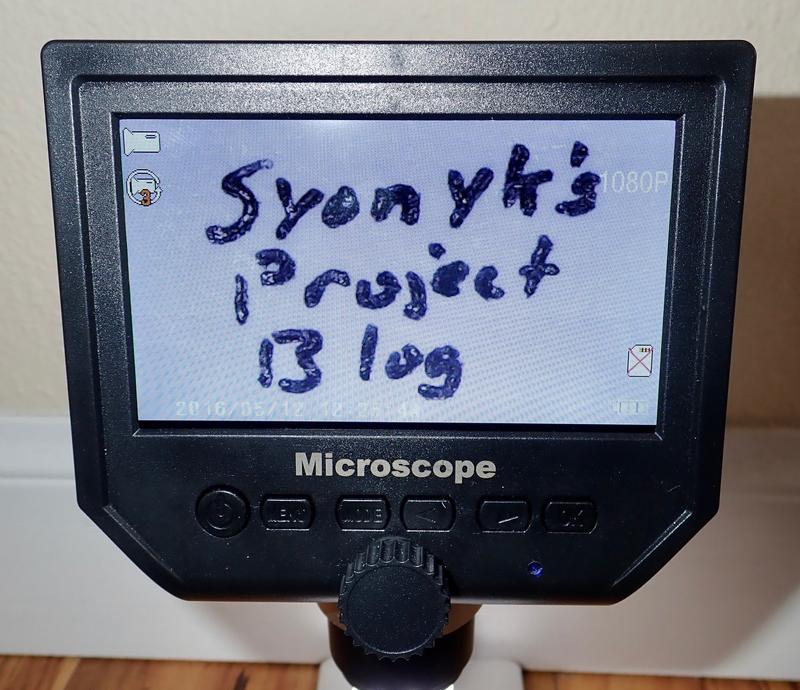
The G600 “1-600x” 4.3” Microscope
Or, at least, sort of “make-a-bit-bigger-scope.” Because it’s sure not 600x or anywhere close. The front is pretty simple. You’ve got a focus knob (nicely mechanical), a power button, a menu button, a mode button, two arrows, and an OK button. In the very lower right corner, a blue power LED lets you know when the unit is turned on.
This is a battery powered microscope, which sounds pretty handy - no need to have yet another cord running around your workbench. Plus, you can save images and video to a micro SD card for later review (though the aspect ratio on the images, as saved, is wrong).

The right side of the unit contains the rest of the controls. There’s a LED brightness adjuster (the rotary dial), a micro SD slot (the card, annoyingly, faces with the top of the card towards the screen, which makes removing the card more annoying than it should be), and a mini USB port for charging and interface - it allows you to use the microscope as a webcam if you jump through a bunch of hoops.
The back contains some slots for the stock mount (which is absolute garbage) and a hole for a reset switch.

Moving to the business end, there’s a cone with a small opening for the image sensor, and a rather bright LED surround ring with a rough plastic diffuser on top. Point this at your target of interest, adjust focus, and go. Point-n-shoot operation, really.

I’ll cover the operation a bit later - but, first, let’s see what’s inside!
Opening it Up
With four screws out, the case flips open - most of the way. The control cable isn’t quite long enough to open the case flat, but it’s easy to remove. The cables in here are pretty standard, though I’ve never seen a male to male ribbon cable joiner before like the display uses…
I see a lithium battery and a large warning sticker I’m about to ignore (Should I be using a static strap? Probably. Am I? No. Is this a problem for the work I do? Not usually).

Front Case & Controls
With the ribbons disconnected, the front case is easy to inspect. There’s the gear for focus adjustment, the board for the input keys, and the LCD.

The keyboard is pretty simple - some cheap buttons on the front, pressed by the plastic keys from the case. There’s nothing too exciting on the front but some resistors.

On the back… actually, there’s nothing at all except some connectors and markings. Fortunately, I don’t have to try and decode this, because Elliot Williams over at Hackaday has already worked out the details - the keys are connected to various resistors in a cheap voltage divider, and the signal is the analog voltage. He’s figured out the resistors you can use to get the same voltages too, if you care.

The LCD is nothing particularly fancy - just a cheap 4.3” LCD. Based on the viewing angles, it’s TN, and I’m almost certain it’s not OLED like a lot of the sales pages claim - it looks nothing like an OLED display and has the characteristic inversion of a TN display at extreme angles.

The rear connection is a 30 pin connector, with the backlight driven from the outside pins. What protocol does it use? I have no idea… I can’t even figure out the microcontroller used on this board.

Into the Back Case
With the front out of the way, let’s see what’s in the back!
The most obvious thing is a giant sticker about electrostatic sensitive devices. While probably true, this is really more of a shipping bag sticker, and presumably the sort of thing someone had laying around. I wouldn’t expect your microscope to come with the same sticker, but there might be some sport in finding out what all stickers the factory used!

With the sticker out of the way, I’ve got a battery pack - this is a 605560 2500mAh cell, which is actually quite a bit larger than I expected. If you need to replace the cell in your microscope after time, just find a pouch cell that more or less fits - there’s absolutely nothing special about this cell.
The 605560 designation refers to a 60mm x 55mm x 6mm pouch cell. Is it really 2500mAh? Probably if you squint right, fresh from the factory. I get a more than useful enough runtime out of the microscope, so it doesn’t bother me enough to test the cell.
More realistically, you should remove the battery and not use it. I’ll talk about that later, but the charging circuit is hazardous on mine and shouldn’t be used.

If you’re pulling the unit apart, remember - blue goes up, like the sky. The blue tape on the various connections on the mainboard point away from the board. It’s not always obvious which way the ribbon cable is supposed to fit.

The Mainboard
Pull a few ribbon cables, remove a few more screws, and the mainboard pops out! Careful - the battery is still connected unless you’ve removed it, so try not to short it out on anything.
There’s nothing too fancy here. The USB port is on the left side along with the microSD card slot and the brightness adjustment. The two pin connector to the right of the dial is for the LED ring, the top ribbon cable is the keyboard, the center ribbon cable is for the camera, and the bottom ribbon cable is for the display.
These all have pretty obvious traces leading to the main microcontroller, which is…

A 18270 BDGA725-P63QJ! What’s that? I have no idea, and can’t find a single reference to the chip on the internet (well, you can find it now - not that I’ve offered anything helpful). Sorry. If anyone recognizes it, please let me know.
Next to it, we have a T25580 PW1802 P1M077 - also mystery meat, but likely a flash chip for the firmware. Where do these companies get these things with no obvious datasheets?
Of course, for all I know, the 18270 is a custom SOC designed for being a microscope. It would surprise me greatly if someone went that far for a system like this, but it’s probably cheaper than using a powerful SoC or microcontroller for running camera to a display. These things are everywhere, which tells me someone built an awful lot of them.

You know what weirds me out and concerns me a bit? Boards that appear to be designed for a microphone - with none installed. Why does a microscope need a “MIC1” port that appears to be for a small cylindrical microphone? I’m not sure I want to know. I might open one of these up and take a look before I used it in a sensitive facility, though.
There’s also a TX test point - this might be for serial debugging of the unit, though I haven’t poked at it.

Moving down, there’s also a speaker connection point on the bottom of the board. Why? No idea, but it’s designed for a speaker to be soldered in. This unit seems a lot more capable than shipped, based on the empty spots on the board. That’s actually quite concerning for something like this - it’s a USB capable device with speaker and mic capability. It’s probably not evil, but it sure could be…
The back of the board has nothing interesting except around the USB port, where there are quite a few more missing component spots - missing a diodes, some transistors, a few resistors…

Hazardous USB Charging: Direct USB Connection!
One thing I didn’t see around the USB port is any way of regulating the charging. There’s no obvious charge controller, though if I assume there’s a custom IC handling the system, putting a charge controller in there would make sense. There’s always power to the main IC, and the power button just pulls a line high to power the IC on.
I’m not particularly comfortable without finding the charge regulation (and seeing an awful lot of missing components around the USB port and battery), so I tossed it on a charge and monitored the voltage on the battery pin.
And when I looked over after a while, I saw 5.17V on the port. That’s NOT OK for lithium - most pouch cells are 4.2V fully charged. Fortunately, the cell BMS had kicked in, disconnecting the charging, and when I took the system off the charger, the cell was only at 4.27V - the BMS protected it.
But here’s the thing: the BMS should be a failsafe, not the first line of defense for charging. This is just a pure unregulated USB charging system, and I do not like that one bit. Yes, the BMS will probably keep the battery from coming to pieces, but that’s just a crappy way to charge lithium. Pushing 5.2V into a lithium cell is enough to rapidly make your life exciting in a “toxic fireball” sort of way, and that’s simply unacceptable.
If this bothers you as much as it should, there’s good news: You can simply remove the battery and use it as a USB powered microscope. It draws about 0.25A, so easily within the capabilities of almost any USB port. However, you can’t just use a computer based port - it’ll try to mount as a USB camera, and you can’t use it. You’ll need a dedicated charging port to use this scope as a USB powered scope - but that’s still far, far safer than letting it abuse lithium like it does.

The Lens
Of course, all of this just serves to take an image from the lens and display it on a screen (or store it on an SD card). What’s in the lens?
The lens has a few screws holding a backing plate to the lens assembly. You can get the lens out of the bottom case without removing these - either loosen the screws slightly, or just wiggle. It should slide right out. We’ve got a LED power cable on the left, a ribbon cable on the right, and the focus mechanism in the center. Remember the gear from the front panel? This is what you’re operating when you turn the Big Knob.

With the screws out, everything just pulls apart. The ribbon cable is folded under the backing plate to allow for easy vertical movement. If you feel the need to pull your microscope apart, be sure to replicate the fold when you put it back together to allow movement.

The carrier holds a board at the bottom with the image sensor and three small capacitors. It’s not a very large one, but this isn’t a very high cost device, is it? It’s just a small image sensor minus the optics (which are in the end of the lens assembly).

The back of the carrier board has a transistor and two capacitors. There’s not much on the board. It’s really just a basic interface between the ribbon cable and the image sensor.

At the bottom of the lens assembly, there’s a lens. I didn’t try to remove it, since it seemed glued in, but that’s what we’ve got - a lens, a movable sensor, and a mechanism to move the sensor.

The outside of the lens assembly contains the (quite bright) LED ring, and a plastic funnel that serves to keep stray light from the LEDs from blowing out the image. In practice, it seems to work quite well - there’s plenty of light for the sensor, and the image doesn’t appear excessively blown out.

Everything goes back together like it came apart and it’s time to review things!
Basic Use: Turn it On!
To use the unit, turn it on (hold the power button) and the display will come up after a splash screen (assuming you haven’t listened to my advice about removing the battery). Twist the focus knob until things are focused and you’re good! If the LED lighting is too high, you can adjust it with the dial on the side, but I rarely find anything but full brightness is needed except for very, very shiny items. If there’s enough ambient light you can turn it down, but the LED ring is actually very well suited to illuminating targets.
If it locks up, use the reset button. Playing back images is a good way to lock this unit up.
The Control Buttons
Hold the power button on the left to turn the unit off - obvious enough.
The Menu button takes you into the menus - I’ll cover that later, but there are some nice settings buried in there.
The Mode button, next over, toggles between video mode, photo mode, and “review” mode where you can see what’s on the SD card - though why you’d use this for reviewing photos, I have no idea. The mode is there if you need it.
The two arrow buttons are useful for navigating the menu - but they also have an extra feature. In the photo or video modes, they’re digital zoom controls. You can select a 2x and 4x digital zoom on top of the normal image, which might be handy for tight work (though the image quality drops quickly as one might expect here). It looks like it’s doing some sort of smoothing on the image for the digital zoom levels, so it’s not quite as bad as one might fear.
Unfortunately, this zoom is only for the display - if you take photos zoomed in, you still get the full image. But you can always zoom and crop in post-processing, and a good smoothing algorithm is an awful lot better than what this thing has.
And, finally, the OK button will start/stop video or take a picture. You might ask how one can get a good crisp photo with pushing a button - and there’s a way with the time delay feature!
Menus
When you press the Menu button, you get context menus based on what mode you’re in - either video options or still photo options. Press it again, you get the main settings menu. OK enters a menu, the left/right buttons select options, OK selects, or Menu backs out.
For video options, you can pick resolution (1080p, 720p, or VGA), toggle the date tag on/off, set up motion detection, and set up “cyclic record” - which just records in a loop and deletes old data as it goes. Play with it a bit, I’m not sure I see any reason to use it.
For still photos, you can pick resolution (I’ll talk about this later), Fast View (how long the image stays on screen after you’ve taken the picture), Date Tag, and Timed Photos - the time delay between pressing OK and when the picture is taken. This is great for preventing motion blur - press the button, the microscope waits a few seconds for the image to settle, then takes the shot.
The main settings menu gives you another bunch of options.
- Format: Format the SD card.
- Language Setting: Chino simplificado, Chino tradicional, Inglés, Ruso, Coreano, Japonés, Español, Turco, Hebreo, Talandés, Polaco, Francés, Italiano, Portugués, čeština, and Deutsche.
- Auto Power Off: Off, 1, or 3 minutes.
- Screen Savers (!): Off, 1, 3, or 5 minutes. This blanks the screen until you press a button while the LED lights remain on - no idea why.
- Reset System: Resets to factory defaults.
- Frequency: 50Hz or 60Hz - theoretically this might help with flicker in videos under fluorescent lighting.
- Time Setting: Set the time for the date stamp.
- Video Rotate: This rotates the video 180 degrees (I have no idea when this would be useful).
- Fill Light: Turns the LEDs on/off. You can also turn them off with the dial on the side.
- Version: Software version (1.3.0 on mine).
Photo Resolutions and Aspect Ratios
I said I’d come back around to photo resolutions - because the resolutions it uses aren’t correct for how the system takes photos.
There are 4 resolution options - see if you can tell what’s weird about them:
- 5M: 2560x1440
- 2M: 1920x1080
- 1.3M: 1280x720
- VGA: 640x480
If you recognized that the first three resolutions are 16:9 and the last is 4:3, good for you! The problem is that the camera is actually shooting 4:3 - and it’s getting resampled to 16:9 somewhere in the image processing path.
Does this matter? Yes. Your images look wrong coming off the SD card. It took me a little while to figure out why things didn’t look “right” in the recorded images - but this is square graph paper. It’s square on screen, but not in the recorded image.

Or for something more circuit-boardy, here’s an Atmega 328P from an Arduino - it just isn’t right:

What you have to do is resize the images to 4:3 in your favorite image resizer (or whatever you have laying around). I just smash the 2560x1440 images down to 1600x1200 and let the algorithm in Preview work - it’s not something that needs insane quality.
With that, the squares are all square - as is the IC!

If you’re looking at boards on the display, there’s no problem - it’s only when you take pictures that it gets a bit weird.
What’s the Maximum Magnification? Definitely not 600X.
With the image resizing out of the way - what’s the actual maximum magnification on this little unit?
Unlike any sort of fancy microscope, there’s no adjustable magnification. The closer you get to the object (and can still stay focused), the bigger it looks on the screen. Finding the maximum magnification then is an exercise in setting the focus to the near limit, running the microscope down the stand until it’s in focus, and doing some math. It should get down to about an inch away from the target and still be able to focus.

I’m working with my graph paper here. It’s 0.1” spacing between grid lines (or 2.54 mm, if you prefer those units).

Zoomed in as tight as I can keep it focused, what’s the spacing on screen? A ruler and some estimation gives an edge-to-edge spacing of about 62mm.

That works out to an effective magnification of 24.4x - useful, but hardly 600x.
What about the zoom buttons, though? They work as advertised and get you another 4x (on the screen only). This gets thing zoomed in pretty tight - here’s the “8” on a 2018 penny for reference. You can see it’s not just doing pure pixel scaling - it does look smooth.

But even a 4x zoom on 24.4x? That’s not 600x. That’s 97.6x. I would happily call this a 100x zoom microscope. But it’s not 600x. Not even close. Not unless you display the image on a TV. This is a 4.3” display, so at somewhere around a 27” display, you’d get 600X magnification.
SD Cards, Cell Phone, Laptop, and Camera Screens
Does that mean it’s useless? Certainly not! Even a 25x “honest” magnification lets you see some pretty darn cool things!
To give you an idea, here’s the ® symbol on a Raspberry Pi adapter zoomed in pretty tight. It’s large and you can see the texture in the plastic easily.

And you can have some good fun with various high resolution displays!
Here’s an iPhone 6S screen - nothing fancy, just an old RGB LCD display. I realized after I’d taken these that Night Shift is on - that’s why there’s not much in the way of blue lit up. There’s a larger difference than I’d realized - this is a white part of the screen!

Borrowing my wife’s Pixel 3A (with an OLED display), you can see that it’s radically different. The pixels are different sizes, and the pixel layout is different. This appears to be a “Diamond Pixel” arrangement. If you’ve wondered why antialiasing has been going away in favor of just higher resolution displays, stuff like this is the reason - without knowing exactly what’s going on with a display, it’s hard to do anything accurately.

My “office” digital camera that I use for macro work has a pretty boring looking pixel arrangement. It’s a Ricoh WG-50 - rugged, waterproof, drop proof, and with an amazing macro lens (though I’m not that happy with the mid-range behavior - there’s more distortion than I like).
The pixels on my wife’s Olympus TG-5 (another rugged/waterproof/toddlerproof camera) are weirdly shaped. On both of the cameras, you can see that the subpixels are staggered - the red pixels make diagonal lines instead of vertical.
And for soldering or other sorts of work, it’s a nice enough magnifier. I wouldn’t use it if I were regularly doing a ton of fine detail work, but for my stuff? It’s good enough.
It’s also perfect for showing kids what things look like rather significantly magnified - and that’s an awesome use case.
Stands
There are two stands that these microscopes come with. One is an angled sticky-base sort of suction stand that holds the microscope at a bit of an angle. This is useful for having the camera somewhat out of the way and is a good match for soldering, though don’t expect it to hold particularly tightly to anything but a smooth table.

The other stand is a nice aluminum stand that holds the microscope vertically. The only real downside is that if the target is very reflective, the lights tend to reflect back and blow out surface texture. But it’s a far nicer stand, and more easily adjusted. You probably want this one.

USB Mode
If you plug the device into a computer, it reports as a TIGA USB webcam. It also reports a bulk storage capability and will present the SD card to a computer if you have one installed.
For fun a ‘sudo lsusb -vv’ will get you lots of handy information about things like resolutions and capabilities. The microphone would presumably be routed to the webcam device if it were installed.
Unfortunately, normal camera software doesn’t work with it. You just get a black screen. I expect this is because the highest resolution mode doesn’t seem to work properly.
I’ve gotten the microscope streaming to work in VLC on Linux with 640x480 resolution. The USB output says it should support 1280x720, but I can’t get that working. But it will stream video if you get the settings right!

With VLC on Linux, you’ll want to select /dev/video0 as the device (assuming it’s the only camera attached to the Linux box), then under Advanced options, manually set the resolution to 640x480. You can also drop the caching time - the default is 300ms, which leads to a noticeable lag. Drop it down (it gets a tiny bit weird at 0ms but eventually works out details) for a more responsive device. It should work!

Final Thoughts
I really like this little microscope. It’s a useful tool to have around, and even with only 25x optical magnification, it shows a lot of neat things. It’s handy for surface mount work and I’ve used it for some IC shots in various blog posts. Really, though, it mostly gets used as a “kid wants to play with the microscope” toy. If she wants to look at an Arduino or Raspberry Pi under magnification and ask about parts, I’m certainly not going to stand in her way!
But.
The charging situation is just flat out unacceptable. You don’t just run USB to a battery without regulation and let the BMS disconnect the battery when the ~charge is complete~ battery is overcharged. It’s wrong in just about every possible way battery charging can be wrong! If you’re going to use this microscope, open it up on delivery and disconnect a battery wire. The stock charging system (if yours is as non-present as mine is) is unsafe. Don’t use it without keeping close tabs on it. Since it works fine as a USB powered microscope, just toss a battery pack on it or use a phone charger to run it.

I’d love to see if everyone’s version of this mishandles the battery so badly - if you’ve found out, let me know.
And, as always, if you find this sort of post useful, toss a couple coins my way with the donate button in the right column. Or, if you think this would be a useful addition, just buy it with my eBay link - that tosses a few coins my way and doesn’t charge you a penny more!
Comments
Comments are handled on my Discourse forum - you'll need to create an account there to post comments.If you've found this post useful, insightful, or informative, why not support me on Ko-fi? And if you'd like to be notified of new posts (I post every two weeks), you can follow my blog via email! Of course, if you like RSS, I support that too.


