
This week, I’ll be focusing on the side-of-house part of the install - inverters, combiners, and into the meter box!

I’ve used fancy combiners/disconnects, mostly because I just wanted something classy looking instead of the knife switch disconnects I could have used. I really like Midnite’s style.

Solar comes to the house, goes to the inverters via a locally-approved variant to the NEC, and heads out to the grid. How? Keep reading!
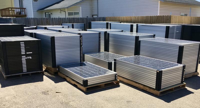
Ground Mount Solar and String Inverters
If you do a survey of modern solar installs, the vast majority of them these days are using microinverters on each panel, with AC coming out of the array. This is partly because it means you don’t have to worry about partial shading on panels (each panel produces what it can, and as a homeowner you don’t get to see the per-panel data that would indicate one is in a horrid place, shaded by a vent stack and chimney most of the day), but mostly because of the rapid shutdown requirements imposed by NEC 2017. There is a new requirement in NEC 2017 that roof mount solar have nothing above 80V after a rapid shutdown, which requires individual panel electronics to handle the shutdown. Some might say Enphase bought themselves a nice handout…
In any case, my ground mount solar panels don’t need per-panel rapid shutdown, and because all the panels in a string will have identical illumination, I don’t have any need for the optimizers.
This means I can use string inverters - and, as a nice bonus, it means I can pick inverters that have an emergency outlet. My Sunny Boy inverters will supply a 2000W backup outlet (single phase only), given sufficient illumination on the panels, and I can then use this and tie into some sort of backup power system. It’s not what I wanted, but it’s what I could get approved.
I have a pair of 6.0-US units for the main frames, and a 3.0-US for the “south” frame (a small south facing array to round out production). These inverters, creatively combined, squeeze tightly into the limits of what my house panel can support (by making use of the 50A “bonus connection” that is not on the main breaker and is normally used for well pumps or similar).
Mounting the Sunny Boys
It’s always a good day when you get to open a few large boxes. The Sunny Boy inverters arrive well packed in boxes (seriously, look at that corner padding - this box is UPS-resistant!) - with what appears to be a missing piece.

The installation manuals I read led me to expect a mounting bracket that everything else hung from. I opened the first box, couldn’t find one. Then I checked the others, and… no, no mounting brackets to be found anywhere. Weird…
But there are those things that look for all the world like mounting holes down on the lower half. Plus, of course, the giant cast heatsink at the top - this heatsink should dump most of the heat coming out of the inverters and, in the process, drive a bit of convection up through the channel in the back.
A bit of poking around the paper manual in the box (as opposed to the PDF one I’d read online) cleared everything up: This is a newer revision that uses the integrated mounting bracket! Just take the top part off, mount the bottom, and everything goes back together. Is it better? I have no idea. But it’s what I have.

To take the unit apart, there’s no reason to take the top panel off - just the bottom one. But, of course, this is me - so off the top panel comes. I’ve covered the details last week, but I was beyond ecstatic to see proper conformal coating on the board! I tend to go on about conformal coatings because they’re such a cheap way to make devices more durable when exposed to moisture, and I’m glad to see it here.

Take out four hex head bolts (two on each side), disconnect a cable, and the bottom part of the enclosure comes off, ready for mounting.

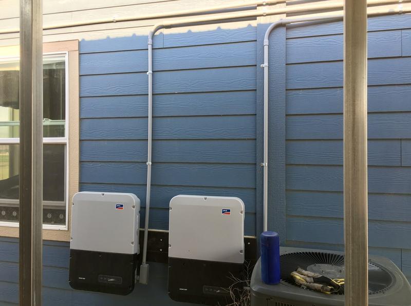
I’m mounting my inverters “split” - one inverter on one side of a window, two on the other side. This allows proper distance for cooling while still fitting them on the side of the house. For the single inverter, mounting is pretty straightforward - find studs, drill holes, drive lag bolts. You’ll want an extension shaft for your socket, because otherwise spacing just doesn’t work well for driving a long lag bolt in. Since my house has 2x6 exterior construction, a 4” lag bolt will be just fine. The slots on one side are vertical, the slots on the other side are horizontal. This allows for some slight adjustment to keep the whole thing level, even if your drill has wandered - very nicely designed!

Sit the top part back where it goes, clamp the sides down with the provided bolts, put the bottom back on, and you have an inverter mounted - entirely useless until some wiring comes in!

The other two inverters, on the other side of the window, required some work with lumber. I can fit both - I just can’t fit both, aligned with studs. So, one large black piece of lumber screwed to the wall later, I can now mount the inverters where I want them, properly spaced, and have them bolted into something stronger than siding.

A few more holes, a few lag bolts, and two more inverters are on the side of the house. Sorry for the shadows - this area is very difficult to get good photos of, because it’s rather shaded by the carport and shipping container. This is by design - the inverters will be in the shade most of the year, and especially during morning/evening peak production. You can see the bead of caulk I ran across the top of the board to help keep any rain from working behind it.

Oh yeah. We’ve got some power conversion circuitry in here!

Useful Tools for Conduit Work
Like most of my projects these days, this is yet more new territory for me - and that means some new tools! I like excuses for new tools!
The first set of gadgets I purchased are wrenches for conduit locknuts. The locknuts thread over the end of a conduit terminator - they’re like a nut, but skinnier, cheaper, and have lugs around the edge. For large ones, a hammer and flat head screwdriver are used, but for small ones? A set of wrenches makes life far easier.

My next problem is related to conduit opening sizes. Some of my boxes have side knockouts for 1/2” conduit termination, but I’m putting 3/4” conduit into them. If only there were some tool designed to drill out conduit openings…

Fortunately, this isn’t a problem - an awful lot of conduit openings in panels are made onsite, to fit what you need. This particular unibit’s bizarre size range (7/8” to 1 1/8”) is explained helpfully at the bottom as being designed for knock-out holes for 1/2” and 3/4” conduit! This will start a hole and expand it (I might put a pilot hole in first), but it’s also perfectly suited to take a 1/2” conduit opening and make a 3/4 conduit opening out of it.
It is also not cheap. I think this ran me $40…

But, properly applied, the hardened steel has made short work of the metal I wanted removed, and my 3/4” conduit end fits perfectly!

Installing the Conduit
Installing conduit is simple enough. Figure out the route, cut your pieces, use PVC cement to cement them together. After some research, one does not typically need PVC primer for conduit - only for pressurized water runs. PVC cement generally melts plastics together, so be quick with it.
This whole project is based around Schedule 80 PVC conduit - it’s thick walled, provides protection from physical impacts (or weed eaters, more likely), and while I don’t strictly need to be using it on the side of the house up high, it’s what I wrote in the plans that got approved, so I’m using it in an attempt to be as close to approved plans as possible. The cost delta isn’t significant.
Conduit bends are typically preformed as 45 and 90 degree versions, so plan around those. However, there is a limit (in NEC) to the number of degrees of bend you can have. For PVC pipe, it’s NEC 352.26: “There shall not be more than the equivalent of four quarter bends (360 degrees total) between pull points, for example, conduit bodies and boxes.”
My runs here are right at 360 degrees, so they’re OK, but weren’t the easiest things to pull. You’ll see why.
Also, in case you’re wondering, you can’t just stuff the wire through the conduit as you run it. NEC is explicit that raceway (of which conduit is a type) must be fully completed before you run wires.
I have a helper. This sort of thing is absolutely fascinating to my son.

For the AC lines coming out of the inverters, I’ve got a conduit terminator sticking through one of the openings. You can see the nut around the threads back on the right - and the tool used to tighten it. Works perfectly! I have another terminator and nut up front so you can see how everything works.

A short stub of conduit extends to the junction box/pull box (if you need more than 360 degrees of bend, you’d better use one of these - I’m using them for the final 90 degree bends into the box and because they’re tighter than a bend). Conduit then extends up, secured at proper intervals by conduit straps.
Thermal expansion is a thing for conduit, and I’ve hopefully left enough slack in the system to let things contract in the winter as needed. I didn’t install these in the heat of the day, so they’re at a midpoint in terms of temperature ranges. Ask me in a year how that’s worked out!

To get to the other side of the meter, and around the windows, I could have gone down or up - but up seemed the easiest path. There was less in the way, I didn’t have to work behind a heat pump, and I only have one large rigid pipe to jump over instead of a few pipes, outlets, etc. You can see my general strategy here - conduit comes up, bends over, and heads across. See that metal pipe on the right? That’s the main feed from my pole transformer - and I can’t exactly go through that.

So, I’ve built these little jogs to go over it. This is 180 degrees of bend in a short length, but it’s the easiest option that doesn’t involve long pieces of PVC flapping around loosely (which also isn’t allowed).

The jogs just loop over the pipe! The combiner on the other side was located based on where it worked to come down. Yes, that’s 270 degrees of conduit bend attached to each other on the lowest run, and, yes, it did suck to pull wire through.

Unfortunately, I didn’t have things measured quite right, and my first attempt to run a length of 1” conduit into my main panel went… rather poorly. And ended up pulling out the larger knockout. Whoops. A chain of adapters will have to do.

The proper solution for a short corner like this is a length of flexible conduit. You can find it such that you just glue the other PVC in, and it makes a tight corner a lot easier to assemble. With a few more runs, all the conduit is finished.

Pulling Wire
The next step is the most annoying - pulling wire. I dug up a 100’ bit of wire pulling tape (longer than I need for here, but a useful backup if the plans I have for the in-ground conduit don’t work as well as I hope).
The process, on paper, is pretty simple. Stick the metal bit through the conduit, attach wires, pull them back through. The actual details are, of course, a bit trickier, and I won’t claim to be any good at this. One of my frustrations on this project is that I’m only doing enough to barely start to get the feel for a task when I’m done with it.
In general, you don’t want to pull a “blob” through the conduit - you want to stagger the wire so it’s a smooth cone that starts pulling through. For my layout, having that 270 degrees of corner right at the start makes things harder as well. I pulled from the combiner boxes over to the inverters, as the inverters are lower and let me put my weight on the tape.

Apply force, and you get to check your conduit mounting in the process. If the conduit isn’t well mounted, you might pull a clip or two free.
It also helps, massively, to have someone at the input side making sure the wire isn’t tangled and pushing it in as you pull. Definitely recommended, and, no, a 5 year old isn’t terribly good at this…

I don’t have better pictures of the process, and as a general rule of thumb, you may safely assume that the fewer pictures I have, the more the process sucked. This wasn’t a fun evening of wire pulling. On the other hand, I didn’t use any wire lubricant, so the struggle is expected.
Wiring it Up
Poke the wire into the actual boxes it needs to be in, and hook it up!
I’ve got plenty of loose wire in the junction boxes, and these runs aren’t tight. There should be plenty of slack, at both ends, for wire contraction in the winter (at night - during the day in the winter, they should get some heat from current).
Neutral bus bar is lower left, isolated from the box. Ground bus bar is lower right, connected to the box. You can see the combiners up at the top - they’ve got alternating tongues that allow the input (or output) from breakers to be combined.

A little bit more wire and a lot more visual clutter later, the whole combiner is wired up. I tried to keep it neat and tidy with as few wire crossings as possible.

One might think “pushing wires a few feet through conduit” is easy, but with a flexible elbow in there, it’s not. The wire ends hang up on some steps and won’t push through. Fortunately, there’s a solution that doesn’t involve snaking tape through a live panel - just make a loop and tape stuff up. Worked great!

The other shutoff is just a shutoff - not a combiner. Here, I routed the wire straight through the breakers and didn’t bother with the combiner busbar, as there’s nothing to combine. Fewer parts mean less to go wrong, right?

Wire runs from the combiners into the breaker box, which is a dusty mess I’ll avoid showing off, and into the backfeed breakers. For inverters that detect loss of grid and stop inverting, you shouldn’t need breaker tiedowns. Hopefully.
On the inverter sides of the runs, simply strip off about 18mm of wire insulation (per the manual) and shove it into these connectors (detailed in the previous post). They’re spring loaded and hold the wire firmly in place without needing screw terminals.

AC Side Finished!
In theory, this finishes out the AC side of the system. I’ve got everything run on the side of the house from the inverters to the panel - though I’ve not tried powering stuff on yet, because the commissioning guide says to turn on the DC side of the inverters first, which requires inspections, and… yeah. I hope these things really work when powered on!
Comments
Comments are handled on my Discourse forum - you'll need to create an account there to post comments.If you've found this post useful, insightful, or informative, why not support me on Ko-fi? And if you'd like to be notified of new posts (I post every two weeks), you can follow my blog via email! Of course, if you like RSS, I support that too.


