
It’s been a little while since I did my Roomba i7 teardown, which must mean it’s time for another Roomba related teardown! This week, I’m diving into the “clean base” - the big vacuum base gizmo that sucks dust out of the bin, automating a lot of the cleaning process. Plus, this base sits far better on carpet than the normal docking station - so what’s inside? Quite a bit!

Unfortunately, this teardown isn’t just a teardown. It’s a postmortem analysis of why it’s really, really important to not let this your Roomba anywhere wet - because if the clean base sucks water, it’s likely to totally destroy the controller board. Which, of course, you can’t get separately.
So, join me at the end of the decade for a teardown and failure analysis!
Roomba Clean Base: Self Emptying Goodness
Most people by this point are familiar with the concept of a Roomba, if not the actual execution. It’s a little vacuum robot that runs around your house (depending on the model, somewhere between “intelligently” and “crash into stuff and go a different direction”), sucks dirt up, and puts the dirt in a little bin on the robot.
Then, once Tenser’s Rolling Disk has either been put back on the charger or has found its own way back (again, depending on the model), you empty the bin, remove hair from the rollers, and it recharges to try again.
The obvious problem with this process is that you have to empty the bin out regularly. It defeats some of the convenience of the Roomba. Also, if you have a particularly debris-prone house (pets, small children, lots of dust), the bin can easily fill up midway through a cleaning run, leaving the Roomba either trying to shove more dirt into a full bin, or making you empty the bin out mid-run.
iRobot neatly solved this problem by making a big vacuum to empty out the little vacuum! The clean base has a mains-powered 1000W vacuum motor (I know the rating on it now), and sucks the stuff out of the Roomba into another little bag for later disposal.
Practically, they’ve also created another consumable for you to buy on a regular basis. The bags aren’t officially reusable, and while you can reuse them a few times if you’re creative, they are the filter mechanism as well and can’t easily be cleaned out.
Death of a Clean Base
As it turns out, a clean base is not waterproof. It’s actually not even marginally water resistant. If a Roomba sucks up water (which, it turns out, it will happily do if wading through some water on the floor), and the clean bin empties the water out of the Roomba’s bin, it will destroy the clean base alarmingly quickly. The water flows into the clean base’s bag, collects a wonderful collection of (conductive) stuff as it percolates through the bag, drips through the open housing of the motor, and down over the main circuit board - where it fries the board completely. We’ll get there, but if you think your clean base has taken water, unplug it immediately. Mine probably would have survived if I’d done that and cleaned it, but as I realized there was a problem when the vacuum motor randomly switched on (and stayed on), paired with the distinctive smell of scorched circuit board… well, it’s now a mostly worthless pile of scrap. But at least I can get a blog post out of it.
Outside the Clean Base
The Clean Base is a nice looking home appliance. It sits up against a wall and plugs into an outlet. Instead of the small charging plate of the stock Roomba charger, there’s a large plate for the Roomba to roll on - and an opening in the rear for the bin to empty through. The bag lives in the top, and it’s a well built bit of machinery.
There’s also a stylish gloss dividing line between the upper and lower parts of the assembly.

If you don’t have a clean base, you may be wondering how, exactly, the Roomba empties the bin out - because there’s no obvious way for the bin to empty (if you have a standard i7). The trick is that the clean base actually comes with a different bin - with a port in the bottom for emptying! This bin also has a small wheel on the back to help guide the bin up and over the plate, I suppose (I’m not actually sure why it needs the wheel). The port on the bottom of the bin lines up with the emptying port on the base and all the dirt gets sucked out. This process also does a halfway decent job of sucking dust off the pre-filter, though you’ll still need to clean out the main filter in the Roomba on a regular basis.

The major opening on the Clean Base, and the only one you’ll interact with regularly, is the lid on top. This is where you put the vacuum bags, and where the debris from the Roomba eventually ends up after a rather twisted path.

Inside, there’s a chamber for the vacuum bag. The motor is at the bottom with a filter over it (keeping large rocks out, mostly). On the left, the bag slides into the guide rails. When you close the lid, that wedge pushes the lever over, driving the vacuum outlet into the bag. When you open the lid, this retracts and the bag comes straight out! If you find the bag stuck, check the lever position, but I really can’t imagine it getting stuck - the spring is quite strong.

Towards the bottom, the large plate provides a stable base for the unit. The Roomba is emptied through the opening in the base. And, as near as I can tell, the communication is entirely through the IR-transparent black plastic glossy area in front. I didn’t find any evidence of anything fancy putting a signal on the charging pads. There’s clearly communication from the charging station to the robot, but I don’t know how much goes the other way beyond “I’m here, please empty me.” Which could be detected by starting charging. It looks like there are some IR receivers on the board, though - we’ll get there later.

The emptying port on the base doesn’t have any sort of rubber sealing surface, but it seems to suck against the Roomba’s bin more than tightly enough. Dirt flows through the small opening, under the base, and up the back into the bag.

On the underside, there’s the normal product label, a bunch of screws, and the dirt path (which can be removed if something gets wedged in there).

The product label has some interesting details. This is an ADE-N1, don’t get it wet (duh), and a power rating that makes no sense. 120V @ 12A is 1440W, not 1200W. I don’t actually know what it pulls (since it’s now rather broken), but somewhere in the 10-12A range. Output voltage for the Roomba is 20.5V (a pretty standard laptop charging voltage), for a total charge power of about 26W.
The marketing name is the “Clean Base,” but everything internally refers to the “Evac Dock.” You’ll see that throughout the rest of the teardown.

Starting the Disassembly
Disassembly of something like this without a manual is pretty straightforward: Remove every screw you can find, and then pry/pull/wedge until something moves or breaks. Repeat until done, ideally with as little breaking things as possible. Remember: Everything like this is built to be assembled cheaply, so other than a few clips, it probably comes apart without heroics as well!
The easiest looking part to remove is the plate for the cord winder. The power cord loops around here as needed to give you the right amount of cord to plug in to the wall. It works quite well - you can see the left/right exits at the bottom, and how you loop the cord gives an awful lot of flexibility in the cord length.

Two screws come out, the plate pops off, and… why, look! Some sort of communications port! Undocumented, of course - but this allows some level of communication with the board once the unit is assembled. I’d guess it’s a pretty competent communication bus.

Working around the unit, the top of the vacuum bin comes off easily as well. It’s just a clip fit, so open it all the way and keep trying to open it - it’ll pop right off!

On the bottom, the screws around the dirt path come out (they’re captive screws - convenient!) and the dirt path comes off. This is the only externally user serviceable part, as far as I can tell, and you can remove it to clear a clog. The left side is smoothly curved to guide things up into the vertical part of the vacuum path.

With a bit of work, the bottom pulls away. The bulk of the vertical vacuum path is attached to the bottom, and would wiggle out with a bit of work, though I didn’t bother removing it.

With the bottom removed, you can see the (fried) circuit board, as well as the metal prongs that contact the charging pads on the Roomba. For reasons I fail to understand, the Roomba manages to gunk up the charging pads on a regular basis. Cleaning those helps a ton when it can’t figure out how to charge. You can see how wet thing are down here. That’s why I’m doing this whole teardown.
The single screw in the center is all that holds the top plate on - it’s mostly secured by the bottom plate.

Take the screw out, and the bottom plate comes off, leaving just the vertical stack.

The next part of the disassembly took a while to figure out. There are two screws in the back, but they’re not enough to free up the plastics.

I could pull the case open slightly, but it didn’t reveal any obvious screws that would help me get further in. Those screws at the far end are clearly not intended to be removed from this far up - it’s just not how you build a device for assembly.

Out of other ideas, I decided to investigate the stylish dividing line further. It’s reasonably rare on modern consumer electronics to have things present that are totally useless. Around the back of the unit, a bit of prying on the plate at the center popped it free, revealing the ends of the divider. It feels a lot like some sort of thick plastic tape…

The tape comes off easily enough - revealing more screws! Two on the rear, two on the front. So, of course, I removed them.

With those screws removed, the back of the unit (containing the diagnostic port) comes off, revealing the back of the circuit board. The AC plug slides into this part of the housing, so that has to slide out before you can remove the back case. The big cylinder up above is the vacuum motor housing. Notice the opening on the right side of it. This is where the air from the vacuum motor comes out, colliding with the foam noise baffling before working around to the grille on the left. The upper air handling section is separated from the lower electronics section by a plate that mostly keeps the air routed out the side. Unfortunately, this plate is far from waterproof.
You can see the light green canyon between the AC section of the board (around the outside) and the low voltage DC section (top left). This sort of isolation is important for safety, and is the sort of thing missing on a lot of cheap Chinese gizmos. Here… it’s more than a little bit excessive, but that’s fine!
The weird black disc on the top left connects, via a hose, up to the vacuum chamber. It’s a vacuum sensor used to sanity check the process.

I’ll dive into the circuit board as a separate section, because there’s all sorts of interesting things on there worth a good look!
Continuing on, the front case comes off. The status LED is the gizmo on the circuit board towards the top, near the noise reduction foam. The opening on the left is where the vacuum air escapes, having hit the foam and gone around the sides. This approach keeps the roar of the vacuum damped, at least slightly. It’s still quite loud, though - you can’t have a conversation near it while it runs, and it’s more than enough to disrupt a sleeping 18 month old if you screw up the timing.
The black, IR transparent plastic is also part of this section. It looks removable, which makes sense as it’s built from something different than the rest of the housing. Of note, I’ve seen zero glue in here so far! The whole thing is held together by screws, and there are only two different types (which are even different colors!).

With the front and rear lower shells removed, all that’s left is the vacuum bin and vacuum motor! The bulk of the weight of the upper section is in the motor - it’s a quite massive hunk of metal.

A few more screws remove the motor and casing. This is the “totally not waterproof” plate that separates the vacuum chamber from the rest of the electronics.

The motor is a Panasonic SDS1000MZR - rated for 1000W at 100V. Odd, given that our power systems are 120V. In any case, this seems to be some sort of custom unit, or custom label, because I can’t find any datasheet for this motor, or even any reference to this model number on the internet. If you’re here because you’re looking for this model, sorry, I can’t tell you anything else.
The big openings on the side of the casing are where the air comes out. This is, quite literally, an insanely powerful motor with an impeller on the end. It sucks air through and blows it out the sides. The air then rattles around in the plastic cylinder until it escapes, slams into the foam, turns around again, and heads out the side of the Clean Base. The black part at the bottom is a rubber donut that wraps around the motor and seals it to the chamber above.

With that removed, you can see the impeller blades. Don’t stick your lips near it - Adam Savage learned that lesson in an early Mythbusters season.

Finally, a still quite wet vacuum chamber. The hose from the base plate connects in the upper left corner. Next to it is the vacuum hose fitting that connects down to the circuit board. There are still a few screws left to remove - they take out the plate that secures the bags.

With the plate out, all that’s left is a mostly empty vacuum chamber! The flexible hose stalk and lever work as described long ago, and the bags just sit in here, filtering and collecting.

The back of the plate contains the opening for the hose, as well as a simple microswitch based unit to determine if a bag is actually installed. When the bag is properly inserted with the shutter pushed down, this switch triggers (you can see the microswitch underneath) and tells the vacuum that it’s safe to run.

This board/switch is a “PCB, EVAC DOCK BAG DETECT,” copyright 2017. The purpose of this particular PCB is simply to secure the microswitch in place and allow the wires to connect. These little boards are quite common in iRobot products - the i7 has a ton of them scattered about. I’m fairly certain this board is hand soldered.
iRobot seems to have a lot of hand-assembled boards and components in their systems. My guess is that, despite their fame, they don’t actually move enough product to justify the investment in machine-produced boards and interconnects. The i7 has a ton of these hand soldered twisted wire interconnects as well. On the plus side, the wire loops through the board - so there’s some strain relief on the wire and it will tolerate stress better.

A filter finishes out the assembly. The mesh is melted onto the plastic, somehow. The bridge in the center prevents the bag from sucking tightly against this - so at least some air can get around as needed.

For as large a device as this is, there really aren’t very many screws - and there are, as mentioned, only two types. They’re even different colors to make it easy! Again, I’m pretty sure the clean base is almost entirely hand assembled - so making things easy is helpful.

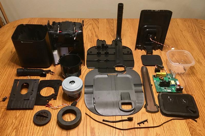
Presto! One disassembled Roomba Clean Base.

The Board: Well Designed, Not Conformally Coated
Before diving into the board, let me rant for a while about conformal coatings on boards, why I like them, and why everything should have them. If you read my blog regularly, you’ll know I comment on the presence or lack of those coatings regularly - and this teardown is a perfect example as to why.
A conformal coating is simply a layer of something, applied over the board once it’s assembled and tested. Think of a clearcoat on top of paint. It protects the board from various contaminants - dust, dirt, salt, water… By having the coating, anything that gets on the board won’t be able to make contact with the components and short things out.
They make repairs a lot more difficult, but they also make repairs a lot less likely in the first place.
For something like a vacuum cleaner, which is literally a device for concentrating dirt, a conformal coating would be an awfully good idea on a complex circuit board located below the vacuum motor when there’s a non-airtight, non-watertight plate separating the motor compartment and the circuit board. Just saying, a $350 Clean Base is scrap because of the lack of a cheap coating.
Coat your damned production boards. It’s worth the cost.
Anyway.
Looking at the back of the board, you can see the giant canyon between the high and low voltage regions - which is excellent. There’s also a resistor chain between the two, which will generally serve to couple the ground planes in a manner that doesn’t allow for much current - even if something has gone massively wrong and a resistor or two has arced over. The lower left corner, complete with scorch mark, is where the power comes in. On the right side, the leads go up to the vacuum motor. And then there’s the pressure sensor in the top left corner.

The front of the board is far more interesting. A large transformer (the box with a yellow wrapper) couples the high and low voltage sides - that’s going to be carrying the current for both running the board and charging the Roomba. A large collection of plastic gizmos serve as the IR guidance system for docking. A small IR transmitter and receiver below it (below the big plastic thing, to the right of the round emitter) are likely the communication interface to the Roomba, and the main microcontroller is at the top.
This PCB is copyright 2018, and is also for an EVAC DOCK.
In the lower right, a fried mess of components has turned mostly to stink.

No, the IC is not conformally coated. It’s just wet.
If you’ve ever watched a Roomba dock, they get into the general area of the base station, wander around for a bit, lock on, and then “wiggle in.” It’s really quite cute. They’re bouncing between two beams, in a manner somewhat similar to an ILS (Instrument Landing System) approach (though an ILS is ideally not “bouncing back and forth”).
As near as I can tell, the lower round emitter broadcasts some sort of general “You’re around the base station!” signal, and the upper gizmo transmits the guidance beam. I don’t know details, and I’m not entirely sure how to go about finding them. The Roomba has an omnidirectional receiver on top, then something more directional internally, and those almost certainly are involved in this process.
All this shines through the glossy plastic IR window. I don’t have anything that operates in the IR bands that this system uses, sadly.

The main IC is an STM32F303 - a 32-bit Cortex M4 based microcontroller. It’s certainly enough to manage something fairly simple like this system! The A120H87 oscillator below is another mystery meat component I can’t find reference to.

Finally, on the back, there’s the vacuum sensor. I was a bit confused by the black disc, as there were no wires going to it, and no obvious pads around the outside. It turns out, that’s not the sensor at all! It just routes vacuum to the sensor on the board!
What does the board do with the vacuum signal? It uses it to determine how full/clogged the bag is, or if there’s some sort of clog in the vacuum system. If there’s not enough vacuum, the top is probably open (as near as I can tell, there’s no mechanical switch on the top). If there’s too much vacuum, the bag is clogged or the inlet is clogged. Between those, everything is fine! I have no idea what the programmed ranges are, though.

The actual sensor appears to be an 8228, or 822B. Again, not much luck finding details on those.

Failure Details
Finally, the fried bits. This corner is quite cooked. I’m not entirely sure if another component used to be here or not - it’s very, very cooked. It looks like there’s a pad for another part, but… short of another reference photo, I have no idea.
This is what burned PCB looks like. You either know what it smells like, or you don’t - and it’s not a nice smell.
My guess is that water, filled with various contaminants from draining through the bag, got enough of a path going here to start conducting - and then it just ran away from there.
However, it’s also possible that the initial failure was somewhere else and this is what finally let go. My clue that something had gone wrong was the vacuum motor starting - and not stopping. Before that, I’d gotten a notification that the communication wasn’t working right, but being busy with the water issues, it wasn’t a high priority on my list. I’m assuming some voltage leaked onto the control lines for the motor transistor, but I don’t particularly want to power the board on again to work out details.

The back of the board shows scorching as well. This is the sort of thing you really don’t want to see on home appliances, but mains voltage will absolutely do this. As far as I can tell, this is before any fuses or such in the board - on the inlet side. It’s leaking between the mains input wires.
Conformal coating would have prevented this.

There’s also what appears to be water residue on the rest of the board, up by the control systems. It could be flux residue, but it looks awfully uneven for that. This probably isn’t doing the board any favors either.

No, I won’t be trying to repair this board. There’s too much damage, too much potential damage, and I don’t have a good reference to work from. Given the weird behavior before I unplugged it, something’s definitely well and truly toast here.
Final Thoughts: That’s a Clean Base!
So, if you’ve ever wondered what’s in a clean base (or “evac dock” as the development name appears to be), this is what’s in it!
Other than removing the tape around the center, the process is non-destructive, and even the tape should go back on smoothly - it’s a thick plastic wrapped tightly, so I’d expect it to re-attach just fine.
Due to a lack of conformal coating, paired with some water ingestion, mine is now scrap, because I can’t get parts for it. And, of course, water damage isn’t covered by warranty.

Such is our modern, unrepairable, IoT world.
This wraps up the 20-teens for my blog! Merry Christmas and Happy New Year! I’ll be back in 2020, with my usual yearly reflections and future plans.
Comments
Comments are handled on my Discourse forum - you'll need to create an account there to post comments.If you've found this post useful, insightful, or informative, why not support me on Ko-fi? And if you'd like to be notified of new posts (I post every two weeks), you can follow my blog via email! Of course, if you like RSS, I support that too.


