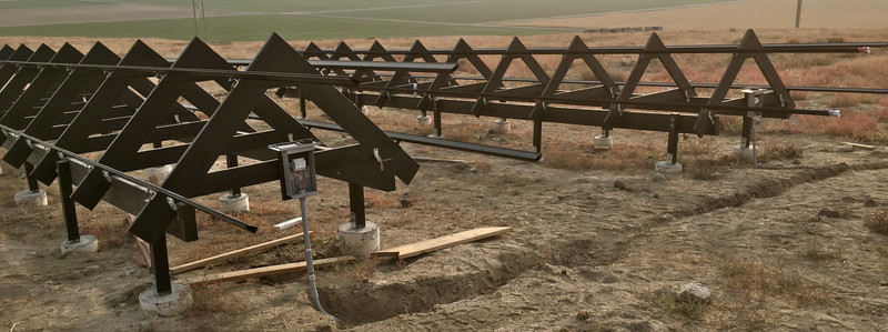

With the frames built and the trenches done, one might think the next step involves mounting the panels - but, the actual next step is to get the rails mounted for the panels. And finish some wiring.

Installing the Iron Ridge L-Feet
There are a variety of mounting systems out there one can use to mount panels, ranging from very nice systems (Iron Ridge being what I use), to just bolting panels into 4x4s (which I’ve also used out on my office frames and can’t really advise). Having gone the “creative and cheap” route before, I decided to do something actually nice this time - and it was absolutely worth the cost. The Iron Ridge stuff works well, is easy to put up, and has a remarkable amount of flexibility in how the rails line up - so if your frame or roof isn’t perfectly flat, no problem at all for panel alignment!
Because it’s smaller and simpler, I worked out the details of mounting rails over on my office test frame before I went about doing it on the big house frames. This is one of the major reasons I put the test frame over there - to work out the details in small scale before going big. A single 17’ piece of XR1000 was plenty long for each of the 4 rails over there, and is somewhat stiffer than the XR100 the house uses.
Iron Ridge provides a variety of mounting options for their rails, and the best option for my project is the L-feet. These get bolted into trusses with lag bolts, and since I’ve no roofing to worry about, I don’t need the options that have flashing built in. If you’re working with a roof, those might be useful - or you can use ones that clip to standing seam metal roofs, ballasted mounts… lots of options. Take a look!
The L-feet have quite a range of adjustment for the rail, and also a bit of adjustment in terms of “up and down the A” - but it’s important to get them pretty close on that front. The amount of adjustment once you’ve stuffed a bolt in there is somewhat less than it appears empty.

For the alignment along the frame, I used the standard tool for making a long, straight line: A chalk line! Make your marks at the appropriate places for the ends, stretch the line tight, give it a snap, and you’ve got reference lines. The red on white is quite visible, whereas the red on the gloss black is far less so - not that it matters.
Where should you put your rails? Check the data sheet for your panels - they should have some mounting advice. For my panels, the left pane mounting range is good for 2400Pa/50psf, and the right one is good for 5400Pa/113psf. Do I need high load mounting where I live? No. Is there any reason to not use it for my install? None. So I spaced my rails based on the high load spacing. There’s literally no reason not to!

The Ls are secured with lag bolts - and lag bolts into wood need pilot holes. Get the proper size drill bit (you’ll probably want a long one), mark it for depth, and go to town. I lined up the L feet on the chalk line, made a quick divot in the center of the slot, then removed the foot and finished the hole. You’ll want to use a square to help make sure the holes are 90 degrees to the surface of the wood, especially the upper ones. Lag bolts going in crooked don’t seat properly on the foot, and I expect it’s a lot weaker that way.

Driving the lag bolts is a source of challenge for a project like this - especially with longer ones. You can use an impact driver to run them in (slowly, exceedingly loudly, with a very real chance of overheating your impact driver), you can turn them in by hand with a ratchet and extension (very slow, quiet, good exercise, blisters), you can run them partway in with a geared drill (fast, tries to rip your wrists off, won’t usually seat them), or some combination of the techniques. Don’t seat the lag bolts fully - you’ll do that after the rails are in place.

Mounting the Rails
Iron Ridge rails are long extruded bits of aluminum, cut to length. For my office, I used XR1000 rails - the big, heavy, industrial ones. These are good for something like a 10’ spanning distance under light loads, and I’m using them on a 4’ spanning distance. So, should be fine!
The difference between the XR10, XR100, and XR1000 rails seems to be mostly just the size of the rails (and obviously the load rating/span distance). They look identical at first glance, but the XR1000s are definitely larger than the XR100s. For the house, I’m using XR100s,because I can’t get black XR1000 locally.
Lots of slots for other bits and pieces to fit in!

How do the rails mount to the L-feet? With these sort of things! You can get this type (“T-Bolt”), or a square headed type for somewhat less money. Right now, the T-bolt is $2.25, and the square top is $1.65. What’s the difference?

The “T-Bolt” type can be inserted into the rail wherever you happen to be working and twisted into place. The square head type has to be slid in from the end and scooted down. Does it really matter? No. If you’re on a tight budget, save some money on the square head bolts. It’ll take a bit longer to get them in position, but there’s no functional difference. For my project, the difference between the T-heads and the square-heads is about $50, and after messing with the T-bolt type here, I used the square head over on the main house install. With a couple hundred foot of rail (or paying by the hour), it would be well worth the cost of the T-bolt types.

In either case, you’ll want to guide the bolts into the L feet. My advice? Take the nuts off while you’re doing this. It will make things far easier, especially on long runs like I had for the house A-frames.

For short runs like my office test frame, you can pretty much lay the rails in and tighten stuff down. Start with the end two and then tighten the middle. Of course, this is using a single 17’ piece of rail. Should you need more than 17’, you’ll need some splices…

Splicing Iron Ridge XR rail is really, really easy. You order a bunch of splice kits (one per splice), and get a bit of aluminum that fits inside the rails, plus some self tapping screws.

Slide the inset halfway into one end, drive the screws. Run the other rail up tight and drive the other screws. This forms a ground bond as well between the rails that meets the various requirements, so there’s no need to ground each individual rail segment. This is one of the nice things about Iron Ridge rails - the grounding is taken care of by the rails, so you can, in theory, ground at one point. I’ve added more grounding points, because my dirt sucks at grounding, but there’s no particular need to.

With the rails loosely mounted and the L-feet loosely mounted, it was time for the part that took a long while - aligning and straightening the rails.
If your rails are up on a roof, this almost certainly doesn’t matter. If you’re not a perfectionist, it also doesn’t matter. But I took the time to align them as well as I could.
This is absolutely a two person job - no way around it. Have one person standing at the end of the rail, sighting down it. Then the other person follows their directions up and down the rail. You can adjust the feet up and down, and the rail “in and out” (away from the frame surface), at least to some extent. If you find something at the end of the adjustment, either relocate it or work on the others to reduce the amount it matters.
Practically, the only thing that matters is the “in-out” dimension. If your rails are a bit wavy side to side, this won’t actually impact panel placement (the rail may be mounting half an inch higher on one panel than the other, and your line of UFOs may not be straight). But, if you’re going to take the time to do it, take the time to get it as aligned as you can. It only takes an hour or two with two people.
Once things are aligned, give them a good crank to tighten them down - but not too much! You can (and I have) snapped the head off lag bolts with too much torque. Do you know what a lag bolt head starting to shear off feels like? You probably will after this project…
Junction Boxes and PV Wire
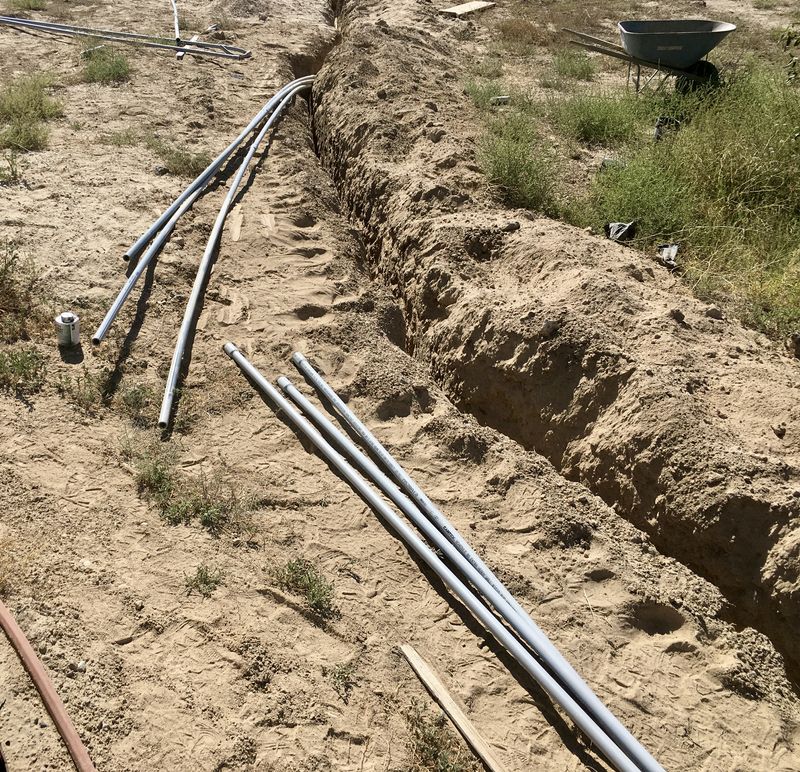
The last step, before mounting panels, is to figure out your wiring protection and PV wire junctions. During the rough-in inspection, I asked the inspector what he wanted to see in terms of protecting the PV wiring (it needs to be protected from people casually grabbing it), and where that extended to. We settled on some plastic mesh (you’ll see it in the next post), and as part of that, I needed to protect the wiring from the panel-side disconnects to an area protected by the mesh (up by the panels).
Before you do this, make sure you’ve planned how you’re going to run the wiring to the panels - and I’d suggest leaving everything loose here, so you can pull in some slack once the panels are up. I got some long MC4 extension cables (they’ve got one male end, one female end, chop them in the middle to run to the fuses), some glands for them (to keep the joints watertight), and some small junction boxes at the top. I think it might be possible, with the right adapters, to terminate the liquid tight flex conduit with a threaded fastener and skip the junction box, but I couldn’t find the right things locally, so went this route instead.
On the subject of PV wire and glands, you’ll find things about “5mm” PV wire or such. It’s hard to tell what, exactly, this refers to - so let me help you.
PV extension wire comes in one of two wire gauges (typically): 12AWG and 10AWG. You can get away with 12AWG for most single panel strings, but if you’re joining multiple strings together you probably need 10AWG.
You can also find PV wire with insulation rated for 600V, and PV wire with insulation rated for 1000V/2000V (for commercial installs). The higher voltage insulation is thicker.
-
12AWG/600V wire is 5mm.
-
12AWG/1000V wire is 6mm.
-
10AWG/1000V wire is about 7.5mm.
You cannot fit a pair of 7.5mm wires through 1/2” conduit fittings no matter how hard you try. There simply isn’t enough room. For home solar, most of the glands you’ll find are sized for 5mm or 6mm wire, so make sure you get the correct stuff (12AWG/600V should work for just about anything). Lessons learned.
In any case, I’ve got the PV extension wires routed through the gland, through the junction box (which is properly grounded - you’ll notice the ground wire looping around), and down the liquid tight flex conduit into the main disconnects below. I thought about just shoving everything down a single piece of conduit, but the glands were 1/2” threading. I probably could have run everything down a single conduit, but then I’d have 4 conductors, have to do derating calculations (potentially proving them to the inspector), and two bits of conduit just seemed the easier option. It keeps everything simple and separated.

Neat, Tidy, and Grounded!

And just about ready for panels!
But that’s the next post.
Comments
Comments are handled on my Discourse forum - you'll need to create an account there to post comments.If you've found this post useful, insightful, or informative, why not support me on Ko-fi? And if you'd like to be notified of new posts (I post every two weeks), you can follow my blog via email! Of course, if you like RSS, I support that too.


