
One interesting experience with the ESP8266 modules, as received from Amazon or eBay, is that they come with a huge range of firmware versions, and a huge range of flash chip sizes.
Some of them can self-update to some version or other, but I’ve found that this isn’t particularly reliable - and doesn’t work at all on the cheapo versions that ship with a 4Mbit (512kb) flash chip.
In this post, I’m going to show you how to easily update an ESP8266 module (I use the ESP01 and ESP02 because that’s what I keep around) to the latest firmware - currently AT version 1.3.0.0, SDK version 2.0.0.0. These instructions should remain reasonably current, though if the instructions stop working, please let me know in the comments so I can update this post!
I explain how to build some ESP8266 test/configuration/updater boards, so you can have one handy for all your projects. And then, I provide some documentation on how to actually update the firmware - even on the 4Mbit flash chips.

Here’s the result: The latest firmware. On everything.

If you’re at all interested, read on!
Interface Board Parts
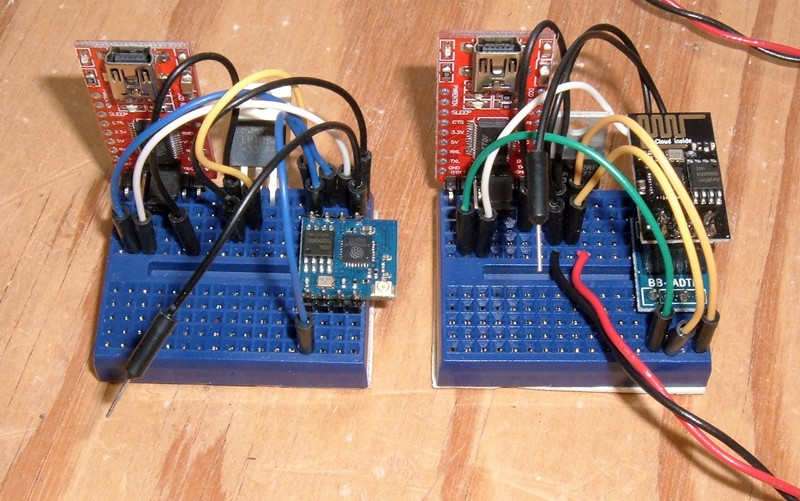
When I’m working with the ESP8266 modules, I use a small breadboard for updating, configuring, and testing. This is the end result for the ESP02 (at least, for mine). There are several pinouts, so your board may look slightly different.

Parts List
You need a few different things for this. I get my parts from eBay, though you could probably find the same thing on Amazon.
FTDI 3.3V TTL Serial Adapter. This adapter is a USB device that outputs a TTL serial level (0-5V or 0-3.3V) instead of the +12/-12V swings of RS232 communication. You need this to talk to the ESP8266 - and it should be set to 3.3V (though in reality, 5V works just fine).
170 Socket Breadboard. This is the base to tie everything together - it’s much easier to work with than soldering a prototype board up, especially if you’re dealing with different pinouts. If you have a large breadboard, that works too, but I like having some of the small ones around for adapters like this - I just leave them configured to reuse.
3.3V LM1117T Voltage Regulator. This is a simple 3.3V regulator that is useful if you don’t have a better way to get a 3.3V power supply. The Arduino 3.3V rail is not enough, so don’t bother going that way. I provide a 5V input from USB, and this drops to 3.3V at up to 800mA. Works perfectly!
Solderless Jumpers.. You can make these out of solid 22 gauge wire, buy a kit, or whatever. Multiple colors are nice, though.
USB Cable. I use this for my 5V power (that gets regulated down to 3.3V). You can use an existing cable if you have one, or build such a thing yourself (what I do). If you’re dealing with stranded wire, you’ll need to solder the stripped ends to create a solid bit to insert.
ESP8266/ESP-01 Breadboard Adapter. This is (somewhat obviously) only needed for the ESP-01 - I’ll explain why later.
Building the ESP02 Adapter
I’ve been using the ESP02 for most of my projects, as the external antenna connector is a requirement for what I’m working on.
Regardless of which device you have (ESP01, ESP02, or any of the other modules), you’ll need power and communication.
This is the USB to TTL serial adapter you’ll be using. The FTDI drivers are part of most modern operating systems, though you can find them easily enough if you need them for an older OS.

There are three pins of interest here: RX (second from the left), TX (third from the left), and GND (far right). You can safely ignore the rest of the pins for this project.
The jumper in the center selects between 5V and 3.3V levels - you want it set at 3.3V for the ESP8266 modules. A bunch of research indicates that they are 5V tolerant on the IO pins, but there’s no need to use 5V here, and it’s just a jumper away, so use 3.3V.

This is the voltage regulator I use - a LM1117T 3.3V regulator. They’re just a basic voltage dropping regulator that wastes the rest as heat, but going from 5V to 3.3V at a few hundred mA isn’t going to waste much energy. The left pin (-) is ground. The right pin (P+) is the input voltage (keep it below 20V, but 5V is perfect here), and the center pin (3.3) is the 3.3V output. Simple enough!

Finally, you need a way to get 5V into the board to regulate down to 3.3V. I use one of my prebuilt USB-to-5V cables, which consist of a USB A end with only the voltage lines connected. My hubs and battery packs (Ingress player, have quite a few of the battery packs laying around) are reasonably tolerant of me doing this. You could also chop the end off a spare USB cable and tin the power wires, or use a bench power supply.

Start the assembly by putting both the FTDI adapter and the voltage regulator in the breadboard. If you’re not familiar with breadboards, each of the vertical rows on either side of the center is connected together - so I can put up to 5 connections on the same row and have them be connected. This also mandates how the parts are aligned - were I to put the regulator in on the left edge, all the pins would be shorted together.
Put the ESP02 in as well. I just soldered header pins on for this. It’s convenient to put the two rows of 4 pins in a breadboard when you’re soldering them on, by the way - a breadboard holds the pins at exactly the right spacing.
At this point, each inserted pin is on a separate bit of breadboard - ready to be hooked together!

This is where I remind you, again, to check your pinout. There are several ESP02 pinouts I’ve seen out there, and you need to use the correct one. It’s unlikely to damage anything if you wire it wrong, but it won’t work.
The first step is to wire up the ground connections so everything has a common reference for 0V. Here I’m using two black jumper wires to connect the voltage regulator negative pin to the FTDI GND pin, and also to my ESP02 GND pin. The negative wire from my USB power adapter comes into that row as well (you can see how all the ground pins come together in that one row).

The next step is the power wiring. The FTDI adapter is powered over USB - so no need to power it (however, it won’t power the whole setup). The red wire from my USB plug is a +5V wire. This goes into the “P+” leg (the right most leg) of the voltage regulator. Coming out the middle of the regulator is the 3.3V regulated output. This needs to run into the VCC pin on your ESP02, as well as the CH_PD pin (if this is brought out - not all of them have it exposed, and if yours doesn’t have CH_PD, you don’t have to run that wire anywhere else). VCC is what powers the chip, and CH_PD is the chip enable. If it’s brought high (to 3.3V), the chip is powered on, and if it’s low (0V), the chip is powered off. However, it won’t float high on its own - you have to bring it high. That’s what the orange wire is for. Check your pinout!

Finally, the communication: serial TX and RX. TX from the ESP02 goes to RX on the FTDI adapter, and RX on the ESP02 goes to TX on the FTDI adapter. The ESP02 transmits on the transmit pin, and if you want to receive, you need to wire that into the receive pin on the FTDI adapter.
For those old enough to remember, this is what a “null modem cable” did - instead of having the serial pinout setup for talking to a device, it swapped the TX and RX pins to talk to another computer’s serial port. Slightly newer, one had to use a crossover cable for older Ethernet standards to directly connect two computers, which was the same concept. Now everything automatically figures it out.

That should just about do it for testing! If you’ve got an ESP02, skip ahead a bit. If you have an ESP01, your adapter board is next!
Building the ESP01 Adapter
The ESP01 is another common form factor for the ESP8266. It has a built in antenna, instead of requiring an external one. It’s fine for inside projects that don’t require much range, or smaller deployment ranges outdoors.

Instead of pins on each side like the ESP02, the ESP01 has a 4x2 pin connector. This is a problem for breadboards, because there is no way to plug this into a breadboard with all the pins broken out - and you do need all 8 pins separate.

Adapters to the rescue! You can find useful little adapters like this for very little money that take a 4x2 connector and break it out wide enough that it can go in a breadboard, straddling the center. You will need one of these. They’re also convenient for NRF24L01 boards.

Building the adapter is basically the same as for the ESP02, but with the adapter instead of the ESP02, and different pins. Follow your pinout diagram. Here, I have power and ground wired in - one power pin to VCC, one to CH_PD (which seems to be commonly brought out on the ESP01).

A bit more wiring and the communication TX/RX lines are in, with the ESP01 seated in the socket. Ignore the stray black wire for now - that comes around for programming later. Where does the white wire go? Check your pinout!

Testing the Adapter
For either board, the next step is to plug the board in and test the adapter to make sure things are working.
You’ll need a serial monitor for this. There are quite a few options, but the Arduino serial monitor is a really easy option for all OSes, and makes sending CRLF line terminations easy.
Plug the FTDI adapter in first. It’s USB powered, so should immediately come online and be recognized by the OS. Select this serial device (/dev/cu.usbserial-something on Linux or OS X, probably COM3 on Windows) in the Arduino “port” menu, then open the serial monitor.
For an initial test, set the baud rate to 74880. Yes, it’s really weird. Yes, it’s useful.
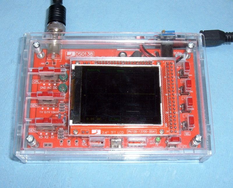
Plug the USB cable feeding the rest of the board in. If everything is working, you should see something like this (give or take) - at least the first lines of it. If that’s the case, then your connections are probably correct!

The garbage at the bottom is the normal system output once things are online and the ESP8266 switches to the normal running baud rate.
The default is 115200 baud for this - so switch the baud rate around. Make sure the line ending selector is set to “Both NL & CR” - the device looks for CRLF at the end of a line.
If all is connected properly, you can type “AT” and hit “Send” - you should see “OK” come back.
If you want to see the current firmware version, “AT+GMR” will give you these results. In this case, the firmware isn’t ancient, but it’s not recent enough for my tastes.

In any case, if this is working, you’re good to go for the next steps!
Getting the Latest Firmware
Next, you’ll need to get the latest firmware. Find it here: http://espressif.com/en/support/download/sdks-demos
You want the most recent “NONOS SDK” - that’s the AT firmware.

Download it, unzip it somewhere convenient. You’ll need it shortly!
Firmware Update Mode
To flash the firmware, you’ll need ESPTool. It’s a Python based flasher for these gizmos. Follow the install directions for your OS.
You also need another jumper to tie pin GPIO0 to ground. Check your pinout, but this is what it looks like for my ESP02 - CH_PD pulled high, GPIO0 pulled to ground.

If you power on the ESP02 with the serial console set to 74880, you should see something resembling this, then nothing else:

If you see that, congratulations! You’re ready to use ESPTool. Note that you will need to close the Arduino serial monitor before you run any esptool commands. If you get a response of “Error: Cannot open port” or something like that when you try to run esptool - close the Arduino serial monitor (or whatever serial monitor you happen to be using).
Boot vs Non-Boot Mode
There are two ways to flash the firmware: Boot mode, and non-boot mode. The difference is simple: Boot mode allows for CIUPDATE updating, non-boot mode is what it is, without any online firmware updates.
Of importance: You cannot install a boot mode firmware on a 4Mbit flash chip. There’s no room.
You can install the firmware either way if you have an 8Mbit or larger chip, but personally, for embedded devices, I don’t want a chance of the firmware changing out from under me without me knowing about it. Yes, I’d probably have to install the update from the serial prompt, but… I just don’t like that concept.
Also, regardless of the flash chip size, you can install the non-boot firmware.
Installing the Non-Boot Firmware
If you’re not sure what you want to do, this is the way to go - it should install on anything.
This command is run from the root of the unzipped NONOS SDK package. You’ll need to set the ‘-p’ parameter to your actual serial port (a /dev path on Linux or OS X, something like COM3 on Windows).
These are the offsets for flashing onto a 4Mbit flash, but they should work for larger chips too. If you have an 8Mbit or larger chip, the README file gives you the offsets to use - use those.
The options are pretty straightforward: ”-p” specifies the port to use, “-b” specifies the baud rate to use for pushing the firmware (the default is 9600, which takes forever), write_flash is the command, and then the remaining lines are an offset followed by the file to write to that offset.
esptool.py -p /dev/tty.usbserial-A9M9DV3R -b 115200 \
write_flash \
0x0000 ./bin/at/noboot/eagle.flash.bin \
0x10000 ./bin/at/noboot/eagle.irom0text.bin \
0x7c000 ./bin/esp_init_data_default.bin \
0x7e000 ./bin/blank.bin
It should look something like this when finished.

Reboot the ESP8266, and you should have an updated firmware! Check with “AT+GMR” - at the time of this post, AT version 1.3.0.0, SDK version 2.0.0.
If you want to flash the boot mode firmware that you can later update with AT+CIUPDATE and have an 8MBit or larger flash module, you can do this (offsets for an 8Mbit flash):
esptool.py -p /dev/tty.usbserial-A9M9DV3R -b 115200 \
write_flash \
0x0000 ./bin/boot_v1.6.bin \
0x1000 ./bin/at/512+512/user1.1024.new.2.bin \
0xfc000 ./bin/esp_init_data_default.bin \
0x7e000 ./bin/blank.bin \
0xfe000 ./bin/blank.bin
Check the README file with the SDK for the current offsets depending on your flash size. It’s pretty straightforward.
Final Thoughts
Hopefully you’ve found this useful - let me know in the comments!
I keep these adapters built and laying around when I’m working on anything involving ESP8266 modules. They make debugging and troubleshooting easy.
Since the Arduino software serial library can’t reliably communicate past about 19200 baud, being able to pop a module out and talk to it at 115200 is convenient, if something gets scrambled.
Also: If you try this and it’s out of date - please let me know so I can fix it!
Comments
Comments are handled on my Discourse forum - you'll need to create an account there to post comments.If you've found this post useful, insightful, or informative, why not support me on Ko-fi? And if you'd like to be notified of new posts (I post every two weeks), you can follow my blog via email! Of course, if you like RSS, I support that too.


)