
Every now and then, I find out about something that is simply absurdly cool and useful for the price.
The DSO138 oscilloscope is such a device - you can get one for $25 on eBay!

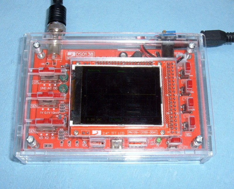
This is a 200kHz-sample-rate oscilloscope that is normally sold as a solder-it-yourself kit for students and hobbyists to assemble. However, if you don’t feel like soldering such a thing together, you can just buy a pre-assembled unit. This is what I did, as I’m way more interested in a working scope than yet another soldering project.
Output is on a built in 320x200 LCD, and the system supports from 10mV to 5V per division, and a timescale from 10us to 500s per division. It also has some built in analysis and a signal buffer that one can use to freeze a waveform and look around.
Is it fancy? Certainly not. Is it $25 shipped? Yup! I’m willing to forgive a good bit for that price.

I’ve spent a bit of time with mine. There are plenty of reviews and thoughts in video form, but my review is in text form, because I don’t like using video for things like this - sorry, everyone who wants me to do video. I’ve also assembled the standard laser-cut acrylic case, and I made my unit USB powered instead of 9V powered, because I like things that run on USB battery packs. I have enough USB battery packs laying around (Ingress player and all) that I can run USB devices anywhere, for absurdly long periods of time.
Interested? Keep reading!
Firmware Updates
The first thing you should do (after verifying operation) is update the firmware. The newer firmware is a good bit nicer than what ships with many of the units, and adds some fancy features.
If you don’t have a “piracy warning” on power up, you don’t have the latest firmware.
You can find the official firmware update instructions here, and the latest firmware here.
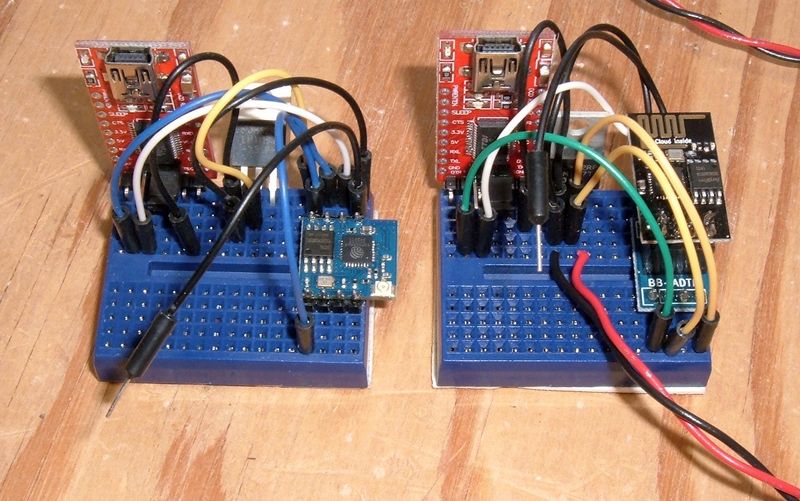
The device has a 3.3V signaling for serial, and I wouldn’t go about assuming it’s 5V tolerant. This means you need a 3.3V USB to TTL serial adapter. These are easily found on eBay.
I’m not going to do a step-by-step of the firmware update process, because the firmware update instructions are quite solid. A tiny bit of soldering, hook things up, run the software. It’s really that simple.
I did build myself an interesting adapter for the process, though. This is three standard breadboard jumpers soldered to a 4 pin 0.1” header (2.54mm for barbarians). Why did I do this?

Because my USB to TTL adapter spends most of its time in a breadboard! I can hook the adapter up to the DSO138, stick the wires in the proper place, and be on my way. You could also do this easily with female-to-female jumper wires. I just didn’t have any at the time.

Really, the firmware update process is that easy. Just do it. Trust me.
Oh, and… you know that calibration procedure in the manual? Do that, too! This is how bad mine was stock - this should be a square wave. Adjust the trim capacitors as instructed. Those overshoots or undershoots will mess with your measurements badly.

Also: This test signal is the wrong amplitude. The test signal should be ~3.3V peak to peak - like this.

Why was it wrong? Because R11 is 1.5kΩ instead of the 150Ω the new firmware expects. It’s a simple change to the board, but if things like this sound concerning, you might not want to buy a cheap DIY scope designed as a soldering kit.
USB Power Source
I wanted a nicer device than just a bare PCB. I set out to install the device in a case, then find a way to power it from USB (the board takes a 9V input for some weird reason I haven’t bothered to trace).
Why? My office is dusty, I tend to beat things around a bit, and I don’t like needing a goofy 9V adapter to power this. I have plenty of USB battery packs that put out plenty of 5V, and I try to power stuff from USB when I can as a personal standard. I’ve hacked up a lot of USB cables to power 5V devices.
Normally, the 9V input comes through a barrel plug - but there’s a nice little JST-XH plug that seems to imply it can power the board. Naturally, I have a large supply of these connectors laying around on a shelf from finding a compatible connector for my ZB206+ battery tester, so I decided to use one.
The DSO138 does, in fact, work perfectly if 9V is applied to this handy little connector.

I also have a drawer full of boost converters - because who doesn’t? These particular units take an input voltage from 2V to 24V, and will boost it up to 28V. They’re rated for 2A (limit on the input side), but many sellers suggest (reasonably) that one might wish to limit it to 1A for longevity - it’s nice to see someone suggest the Standard Chinese Derating in a sales page.
If you’re paying more than $2 on eBay, you’re overpaying.
And they’ve got a micro USB port on the input side!

These are pretty simple to use. Plug them into power, play with the knob on the adjustable resistor until the output voltage is as desired (for this project, you’d do well to desire 9V), and you’re good to go.
Assembling the Acrylic Case
A popular accessory for these little gizmos is an acrylic case. It looks pretty slick, it protects the device from parts coming off or junk falling in, and… well, that’s about it.
In any case, you can buy a case for about $8, or can just order a full unit with case.
It shows up as a bag of screws and some clear plastic. No instructions, of course.

This is what you get if you order one. A weird maze (top left), a few other identical sheets (rest of the top row), a top and bottom piece (bottom row), side pieces (the small ones), some screws, and some buttons. You’re on your own here!

Well, you’re not. I’m here with you - and if you’re looking for a text-and-photos description of how to assemble this thing, keep reading, because that’s what I’m going to provide!
The first step (if you want a clear acrylic case) is to remove the protective paper layers. You can do this initially, or you can do this as you work - either way. I did it up front and used some paper towel to protect them from my work surface.

The first thing you need to do is remove any feet that your board came with - mine has four. Also, if you look on the left, there may be a bit of PCB support that isn’t going to fit the case (the part labeled “126.84*152.16mm”). It just folds off. Remove all that stuff first.
Oh, for entertainment purposes: 126.84mm is 5”, and 152.16mm is 6”. It’s always amusing to see what really weird metric measurements work out to - they almost always work out to something very reasonable in imperial units. The ever-common 2.54mm pin spacing? 0.1” spacing.

Ignore My Modifications
One downside to this stock acrylic is that it fits tightly around the barrel jack, and doesn’t assume that one might want to use something else. I’m weird, so I want to use that little header.
Here’s the problem, though: It doesn’t fit. The acrylic will sit down tightly on top of the pin header, but not with wires attached.

This is easily solved, right? A bit of a trim with a wire cutter, and done. Those of you who have worked with acrylic before will probably be giggling right now, anticipating what I’m about to learn the hard way.

That lesson I learned: acrylic is really, really brittle, and you can’t just go snapping bits off without breaking pieces off. I probably should have pulled out the small hacksaw.
In any case, what’s done is done, and I’ll work around this. If you’re planning to use the barrel jack, don’t do what I did.

My boost converter is wired in, and the wires run through the hole for the calibration signal. A better option might be to desolder the barrel jack and use that hole, but I used what seemed convenient. I can always go back to a bare board, if I feel the need.
You’ll note that it’s running here - the micro USB to 9V adapter works perfectly!

Back to Assembly
Ignoring my hack job on the right side of this panel, the first step is to mount the weird maze-like piece. This goes on the back of the LCD display.
The LCD has a long connector on the right side, and two small connectors towards the left. It pulls off with moderate pressure - do it gently and evenly to avoid bending any pins.
Notice the four small holes in this piece of acrylic. They’re where the display mounts.

Use the four smaller nut and bolt pairs for mounting the screen.

Sit it in place, run the bolts through, and secure the nuts - gently! Finger tight is fine for this project - the nuts and bolts are really small, and the acrylic does not take stress well. Don’t clamp them down. Secure them lightly.
If you’re planning to carry this in a high vibration environment, use locktite (blue would be good).
Once the LCD daughterboard is mounted, it’s a really good time to remove the film and make sure the LCD is square. Notice that mine isn’t. Unless you want to get a few steps in and then have to go back, square it up now!

The next step involves building up the top half of the case. This is done with both of the identical panels with the LCD hole cut out, and the top piece with the button and slider holes.
The next two shots show how things line up. You don’t actually need to mount the LCD on the board for this step (if you do, it’ll just come right back off).
The left slots are for the various sensitivity sliders. The switches are extended up with the red plastic sliders.
Note that there are two identical layers here on top of the maze layer.

The buttons slide through similarly. The crosses are upright as you look at them - the very top layer has smaller holes that prevent the buttons from coming out. You can install them upside down, but they’ll stick way out if you turn the unit over. Don’t do that.

Here’s the actual assembly process. The two identical sheets stack on top of the maze sheet, and then the top sheet stacks over that to cover everything. Be careful about fingerprints and dust - they’ll get trapped if you let them. Run the four long bolts through the corner holes.

Again, the buttons go this way - “upright cross” with the unit oriented normally.

Use four of the nuts and thread them down to hold the top stack together. Seriously, no need for monster torque. Finger tight is fine. If you clamp them down too hard, you’ll crack the acrylic.

The next step involves assembling the unit. If you’ve used this little power-in connector, be sure the wires are out of the way. They won’t fit over the top of the barrel jack - I tried.

After routing wires, the base logic board needs to be joined with the LCD daughterboard. This involves lining up the LCD daughterboard connectors, the bolts, and the switches. The switch handles have to sit between the plastic legs of the red sliders.
It’s pretty simple, but make sure everything lines up before you seat it firmly.

Once the board is set in place, it’s a good time to test things - make sure it powers on and works properly.
Assuming it works properly, use four more nuts and secure the main logic board in place. Again, gently is fine here! If you clamp it down hard, you’re just bending the PCB. PCBs do not like bending.

Remember how I mentioned earlier that you should square up the LCD? If you don’t, you may find yourself, like I did, most of the way done with a radically tilted LCD.

With the PCB secured, install the sides. They interlock in an obvious manner.

Finally, install the bottom of the case. The four cap nuts hold this in place, and secure the whole stack!

That’s it! If you choose to power your scope normally, you’re finished now.
Mounting the USB Boost Converter
I’m not quite done yet, though. I’ve still got the boost converter to mount. I don’t mind blocking the power jack, since I won’t need it.

When I have something I need to stick to something else, I use my 3M Automotive Acrylic foam tape. This stuff is expensive, but I’m still on my first roll, and it’s just awesome. Seriously, I love this stuff. Insanely sticky, foamy, and just holds anything to anything.

A tiny strip is all I need here. Cut to size, stick to the boost converter.

Remove the other side, install, and I’m good! I should really drop some superglue or hot glue over the adjustment screw so it doesn’t wander, but this is it!

Hook the cables up and it’s good to go! Yes, it’s running here… the flash makes it difficult to see.
Operational Notes
You can find plenty of YouTube videos going through basic operation if you’re lost. If you know how to run an oscilloscope, it’s pretty straightforward.
Really, read the manual.
The top left slider (CPL) affects how the signal is processed. GND will ground out the input, and you won’t see anything as far as a signal goes (useful for zeroing the scope). The DC position passes the signal straight through (so you’ll see the DC offset), and the AC position tries to filter out the steady state DC offset and offers you the voltage bouncing about the zero mark (useful at high frequencies, less than ideal at low frequencies). The state of this switch is shown along the bottom of the display (“AC” in my screen).
Below the CBL slider are the SEN1 and SEN2 sliders. These set the voltage per division. The lower left of the screen will show you the current setting, so just play around here - it’s really obvious how things work with 15 seconds of messing around. Remember, this is volts per division!

The button along the bottom is a reset button - it power cycles the device.
On the right side, the buttons are OK, +, -, and SEL. OK will freeze the display (press again to resume showing live readings). SEL chooses which setting to alter (there’s a box around it), and +/- changes the setting, for whatever that means in the particular setting.
Timebase
The default position is the timebase - the time interval per division. Your options are 10us, 20us, 50us, 0.1ms, 0.2ms, 0.5ms, 1ms, 2ms, 5ms, 10ms, 20ms, 50ms, 0.1s, 0.2s, 0.5s, 1s, 2s, 5s, 10s, 20s, 50s, 100s, 200s, and 500s.
Everything 20ms and below will sample a full buffer then display it. Larger times display a “rolling window” - with the position in the buffer shown by the block along the line above the main graph window.
Trigger Modes
The options here are “AUTO,” “NORM,” and “SING.” Auto runs the sampling more or less constantly. It will trigger normally if there’s a trigger event (the green LED will be flashing), otherwise it will just trigger randomly or read continuously (if >20ms timebase). Norm will update the display every time there is a trigger, and Sing will, sadly, not make the unit sing. It will trigger once and then hold.
Trigger Direction
The next option is the “up/down” arrow to the right of the trigger mode. This just chooses between a rising and falling trigger direction.
Trigger Level Selection
The indicator on the right side of the screen sets the trigger level. The currently selected trigger level is shown in the upper right corner of the display.
Buffer Position Selection
The bar across the top shows which region of the 1024 sample buffer is being displayed. You can use the +/- buttons to select where in this buffer you are. This is useful when in any of the “continuous scrolling” modes - set it to the far right side, and you’ll see changes instantly. If you have it in the center, something will happen, and you’ll eventually see the result scroll past. Or, if you just want to scroll around in a buffer, you can use this to look for the event you want to inspect.
Voltage Offset
The left side indicator allows you to scroll the entire waveform up and down - useful when in DC mode, measuring a positive voltage, and you want to fit the whole thing on the screen. A useful shortcut here to know is the “reset zero” operation. Often, if you set the CPL switch to GND (ground), there’s a bit of an offset between the arrow (which should show the 0V level) and the displayed signal. Hold “OK” for a few seconds here and it should reset the zero.
Hold
With anything selected, tapping “OK” will freeze the display and show HOLD in the top left. This is useful to inspect the buffer, though be aware that changing the switches won’t affect the displayed image here.
Useful Shortcuts
This unit (at least on the latest firmware - 060) has a number of useful shortcuts. I’ve documented the ones I know about here.
“Analysis”
If you’re looking at an AC waveform, and want to know some details - max voltage, min voltage, peak to peak voltage, frequency, etc - select the timebase and hold “OK” for 3 seconds. You’ll get an overlay of this stuff.
Reset Factory Settings
You’ve done something and you don’t know what or how to undo it. Hold “+” and “-“ for 2 seconds and you’re golden. Back to the defaults! You’ll probably need to move the voltage selection switches once you do this - it really does reset to the defaults, and doesn’t sample the switch positions on reset.
Reset Vertical Offset
If the vertical offset (the left marker) isn’t showing zero when GND is the current input (ground - should be 0V), select the left marker, hold OK for 2 seconds, and it should reset to the middle of the waveform.
Save and Recall Waveform
Hold “SEL” and “+” to store a waveform. Holding “SEL” and “-“ recalls it.
Center Buffer Position
If you’re off at one end of the buffer, and wish to reset it - select the top buffer position indicator, hold “OK” for a few seconds, and it will re-center.
Auto-set Trigger Voltage
If you hold “OK” for a few seconds when selecting the trigger voltage, it picks the middle of the waveform as the trigger level.
“Analysis” behavior
One of the less obvious behaviors of this unit relates to the analysis display (select the timebase, hold “OK” for 3 seconds to enable this).
If you’re looking at a signal (say, this one), you’ll see a certain set of values.
If you then proceed to fiddle with the switches on the left, you’ll see a radical change in all the readings on the right hand side - they change, drastically.

If you let the scope run for a while, you’ll see that things more or less settle back down to where they were in a few seconds.
What’s going on here?
It relates to the scope’s data memory. This scope has a 1024 sample internal memory. The screen is 320 pixels wide. The weird icon in the top/center of the screen shows where in the sample memory is being displayed.
When you change the voltage settings, the min/max/etc settings are calculated based on the current buffer - determined by the switch settings. So you change the switches, but you haven’t emptied the buffer yet. Once it empties, things are good for the new settings, and the data is correct.
Just something to be aware of.
DC Voltage is Wrong
If you update the firmware to the latest version (-060) and your DC voltages are off by a factor of ~4 (a 4.2V battery shows 1V, a 5V USB signal shows around 1.25V), you’ve got the wrong value of R11. It originally came as a 1.5kΩ resistor. Change it for a 150Ω resistor and it should be correct (mostly) with the new firmware. If you’re really, really picky about calibration, you should get a ~150Ω potentiometer and tweak it for the exact value. I’m not that picky, so “about 150Ω” is fine with me. It’s close enough for my needs.
Final Thoughts & Conclusions
Compared to an expensive bench oscilloscope, this is a silly toy. It’s slow, limited, inaccurate, and generally not useful.
However: If you don’t have a bench scope, and the limitations (mostly the very slow 200kHz sampling) are something you can work around? Go buy one! They’re absurdly cheap, even pre-assembled (which, really, is how you should get it if you’re interested in the result instead of the project).
Since I don’t have the money for a digital bench scope yet, this certainly gets dragged out on a regular basis. Having the USB power adapter is well worth the cost as well - USB battery packs make great little power sources.
Do you have one? How do you like it? Let me know in the comments!
Comments
Comments are handled on my Discourse forum - you'll need to create an account there to post comments.If you've found this post useful, insightful, or informative, why not support me on Ko-fi? And if you'd like to be notified of new posts (I post every two weeks), you can follow my blog via email! Of course, if you like RSS, I support that too.


