
It’s rare to find something this interesting in the Chinese Electronics realm.
What I have here are two different units - that look identical at first glance! And, actually, they look identical until you really dig in and stare at details. But one is really, really good, and one is so comically bad that it probably won’t last an hour in actual use before blowing up.

How do you tell them apart? Is the good one any good? Read on to find out!
The 60V/150W Load Tester
A load tester is a handy little device for applying some load to some power source, and measuring how much energy the source provides (usually in amp-hours, sometimes in watt-hours as well, though that’s rare). They’re useful for beating up power supplies (ensuring they can provide the rated power), and they’re also quite helpful in testing batteries. My interest in this supply is related to testing battery packs for capacity. I have a resistor based load tester I’ve used some, but pulse width modulated battery loading isn’t ideal, and I’d rather have something that draws an actual constant current with a transistor load (which is what this unit claims to do).

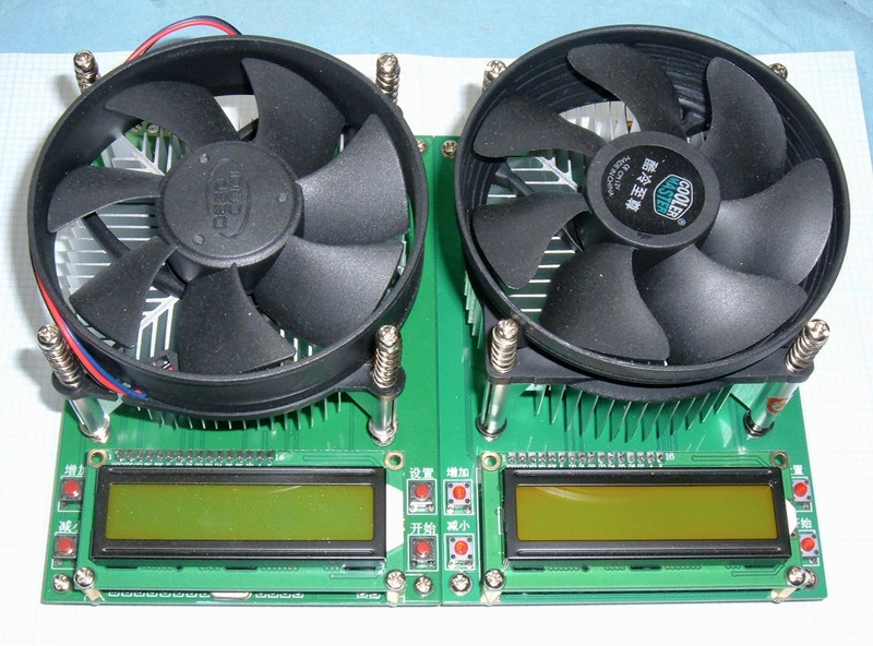
On paper, these two units are identical. These are digital load testers that handle a peak of 60V on the input side, have a nice little console for control and reporting, and can dissipate up to 150W through their quite impressive little heatsinks, powering the fan as needed. It’s certainly not clear that there are two different versions unless you read around a lot.
They can handle up to 10A of current, assuming you stay within the power limits, and they have a configurable cutoff voltage for terminating the discharge, which is great for battery testing. Plus, they support four-wire measurement of power supply voltage, which means that the voltage drop in the wires carrying the current to the tester is safely ignored. It’s helpful for precise cutoff voltages in higher current testing, though 10A is hardly high current. I still like four-wire modes.
You can find both of them, on eBay, for less than $30 - shipped. Ignore the purple fan one - I’m reviewing it later, but it’s not worth buying.
The only problem is that one of them is really, really good, and the other is dangerous crap - and telling them apart isn’t easy. But, it’s doable, if you know what to look for - which I’ll teach you!
What’s Inside?
If you’re a regular reader of my blog, you’ve probably worked out that I really like taking things apart to see what’s inside. This is no exception, though what you’re going to see here is the legitimate unit in pieces. Interestingly, the fake unit is almost identical (even has the same processor), so I assume the differences are almost entirely in the software.
With the standard Cooler Master heatsink off, and the display unit off, the guts of the board are on display. The variable resistor up at the top appears to control the fan speed, the big transistor is in the center for dissipating the load, the wire across the sides is the shunt (the voltage drop across the low resistance wire is used to determine current), and the bottom has the digital control section.

Zooming in in the control section, the main controller IC is a STC 15F2K16S2 - an Intel 8051 compatible microcontroller. Harvard architecture, as is standard for microcontrollers. Digging up a spec sheet, the 15F2K16S2 is a 5V part with 2k of SRAM and 16kb of flash. Plenty of capacity for something like this, and if one wanted, one could probably bolt on a lot more capability in that space. Serial out, anyone? I think the transmit pin is unused… This isn’t the first Intel 8051 compatible unit I’ve seen - the TEC-06 battery tester had a similar processor. Since it’s basically the same thing with lower power handling, I’m going to guess that STC makes a nice line of chips for this sort of purpose!

Flipping the board over, you can see the high current traces. I will say, to it’s credit, the fake unit had these thickened with a solder layer, and you could easily do this if you were regularly running up at the 10A side of things, but I just don’t see a good reason to unless it’s a problem.
In the center, the three pins for the load transistor poke through, and there’s that little “NTC” circle. That’s hosting a thermistor, poking right up into the center bolt-down hole of the transistor, which is perfectly suited for putting a temperature probe in! The reported temperature should be quite accurate from there, and the absolute value doesn’t really matter except for over-temperature protection and fan operation. This should be just fine!

The display board is an absolutely bog standard 16x2 LCD display, of the variety you can find on eBay for under $2 in bulk. Nothing special here. Just a 1602A based LCD, without even a fancy I2C backpack.

I put the disassembly before the operating guide. That’s usually because I disassemble something before I apply power…
Operating Manual
I appreciate single purpose devices that do their job well, and this unit does exactly that. It doesn’t claim to be fancy. It has a very, very simple user interface. It lets you set current, set a low voltage cutoff, and turn the load on and off. There are some buried calibration menus that you access through arcane button presses (on the legitimate unit - the fake one omits these), but only one of those is of any particular importance.
When you power the unit on, you’ll see a brief welcome message (“Welcome to use”) and then the main interface. The top left shows the measured voltage, the top center shows the current amperage, the top right shows the status (“OF” or “ON”), the lower right shows the set current (or the low voltage cutoff), and the lower left cycles through a number of different displays. It shows total amp-hours, time the load has been running, watts, and the load transistor temperature.

It would be nice if the buttons were labeled in English or with more universal symbols, but they’re pretty straightforward.
The left two buttons are “up” and “down” - they change the value selected by the cursor (and values increment properly, so if you increase the “9” in 0.90A, it will increase to 1.00A).
The top right button is the cursor select (you can select the letter or any of the positions in the load current or cutoff voltage).
And the lower right button serves to toggle the load on or off, and a long press will reset the accumulated values (as will a power cycle).

If you use the up or down button on the “I”, the display will change to show “V=” - this is the cutoff voltage, when the discharge will automatically stop. Note that this is the under load voltage (as opposed to the open circuit voltage). It doesn’t matter for power supplies, but for batteries, especially under higher current load, it makes a bit of a difference. Unlike some battery testers, this unit doesn’t pause the load and measure the voltage when determining cutoff.
The unit allows you to adjust the load and cutoff voltages while running, which could be nice if you were looking to load a power supply to the limit. For testing a USB power supply, one might set the cutoff voltage to 4.25V, and up the amperage 0.1A at a time until the power supply cuts off (or the voltage sags down far enough - some just sag and sag but keep providing current, under the assumption that the device will back off).
By default, the beeper is on, so it will run until the low voltage cutoff, then beep and be done. Simple, straightforward, and easy!
While running, by default, the lower left corner will cycle between current watts, amp-hours, time, and temperature. If you want to manually cycle through these, hold the top right button, and then press the top-left button. It will cycle through the four elements each time you press the top left button. If you want to go back to auto cycling, hold the top right button and press the lower left button. You’ll see “Auto” displayed briefly, and then it will begin cycling again.
The Arcane Button Presses
If you want to fiddle a bit more, there are a number of button combinations that work on the legitimate unit. This is a good way to test for the legitimate unit - these do not work on the fake unit!
Software Version
To see the software version, hold both left buttons (up and down) and power the unit on. You should see the software version displayed - mine shows V1.62, which is what other reviewers have seen as well.
Auto Calibration
For automatic calibration, hold down the top right button while the unit powers on. You’ll see a screen requesting the attachment of a power supply that’s less than 20V and that can provide greater than 5A. Once this is done, press the lower right “start” button to automatically calibrate the unit. It performs some variety of magic and ends up calibrated!

Factory Calibration
I’ve not performed this test as I don’t have a precise enough power supply, but one can supposedly factory calibrate the unit with a power supply that provides exactly 10.00V and limits at 5.00A. Enter this mode by powering on with the up and down buttons held to show the software version, then press the lower right (“start”) button, and alternate the lower left and upper right buttons until calibration starts. The manual I found suggests that doing this without the proper precision equipment is a bad idea and can get the unit into a weird state, so stick to automatic calibration.
Accuracy (Legitimate Unit)
A unit like this isn’t any good if the calibration is out in left field. I performed the automatic calibration on my legitimate unit, then wired it up to my bench meter and tested at a few different current settings (0.1A through 5A, because my bench power supply won’t go higher, and I’ve learned my lesson about testing these things on battery packs before I fully trust them).

Wow. There’s good, and then there’s this unit. I’m happy with a percent or so in each direction, but this unit? About 0.15%. That’s good. That’s seriously good for a $30 load tester!
I started out by setting 1.00A. The display showed 1.000A. My meter showed 1.0010A. Not bad! This is close enough that I’m willing to call it spot on, because my meter hasn’t been calibrated in a bit (I really need to do that).

If you request more current than the unit can safely dissipate (it hits the 150W limit), the unit will show the actual current. With my supply set to an idle voltage of 42V, I asked for 5A, and didn’t quite get it. The unit capped at 3.700A indicated (this is really obvious on the display because it shows both the set amps and the actual amps).

Actual current showed 3.7048A. This is an error of 0.13% between the two units - so, properly impressive.

If the voltage drops, the unit will let the current increase towards the set value - so if the unit is capping at 150W, it will hold 150W as the supply voltage drops. It’s useful, but it may not be intuitive behavior (the current increasing over time). Dropping the voltage from my bench supply without changing anything else, the current rose until it sat at the requested 5A.

Actual current was a bit higher than indicated (or requested), but it’s still very, very close (0.08%). I’m entirely happy with how this unit (the legitimate one) regulates.

Voltage is similarly accurate. I did some spot checking of voltages across the range and it’s within 0.01V at the low end and 0.03V at the high end - so about 0.1% throughout the whole range. This is excellent - the accuracy on this device is among the best I’ve seen in units from China. Whoever built the legitimate version knew what they were doing and did a great job. Again, this is within what I consider the tolerances of my meter to be. Very, very accurate.
This unit will dynamically adjust the current to hit the target. You can see it with very low currents in action - if you set it to 0.10A, it may overshoot slightly to 0.12A and then drop back down to the requested rate, which means it’s definitely using feedback. There’s no way to get this precise without it, but it’s interesting to see it in action. I’d be happier if it would store the correction factors for future use so it doesn’t overshoot, but, hey, $30…
Accuracy (Fake Unit)
The bulk accuracy on the fake unit isn’t… good. It’s at least in the same city as the ballpark, but it’s certainly not nearly as accurate - and it can’t even self correct when it’s showing wrong values. I set it to 1A, it shows 1.048A coming through (4.8% error, which is quite gross given how accurate the legitimate unit is), and it refuses to correct. The legitimate unit would be correcting now and finding the correct value based on the shunt, but the fake one seems to lack that feature.

I’d get you the rest of the comedy show, but, unfortunately, before I could get the whole sweep, it failed (again) in it’s stereotypical manner (see below). I did load up my power supply through it, and while the unit was showing 4.44A, my bench meter was showing 4.1A. So, you know, within 8.3% of reality… it’s bad. But that’s not the worst part.
What Makes the Fake Unit Dangerous
The accuracy alone is a good enough reason not to use the fake unit. It’s really, really bad. It can’t find the current you set based on what it’s reporting, and what it’s reporting might be within 10% of reality.
What makes the fake unit dangerous is that it frequently gets into a state where it shorts the load. I don’t understand what causes it, but when I first started playing with the unit (I had the fake one first), I was testing with a battery bank. This seemed, at the time, a reasonable thing to test a battery load bank with. It worked OK, though the accuracy was, as noted above, all over the place.
Then, I turned off the load with the start/stop button, something popped loudly, and the unit wouldn’t work anymore (it powered on, but there was no current passing through). Investigation revealed that it blew the 10A fuse on the circuit board. I replaced the fuse, assumed the power transistor had shorted out, and replaced that as well. Nope. It just… does this thing where it shorts out. For a while. Sometimes it recovers, but usually not.
Further testing using a current limiting bench supply revealed that it would frequently trip into this state. Quick, how much current is flowing through the unit? It’s turned off and is showing no current, so the answer should be zero.

Definitely not nearly 4A, sitting on the current limiter on my power supply…

If I turn it on and request 1.00A, it properly shows that much more current is flowing through, but it doesn’t seem to actually fix the problem. It’s just… shorted. This is what makes the unit dangerous - there are many behaviors a load bank can exhibit, but shorting the load is not one of them!

When I was doing some research on this unit, I found a helpful post over on the EEVBlog forums talking about this problem. As mc172 reports, “I bought one of these for a laugh and received the version without the polarity diagram on the silkscreen. It doesn’t always disconnect the load, instead it shorts whatever you’ve got it attached to. Not good.“ So it’s not just me seeing the shorted output behavior. At least it has a fuse…
The review at #360customs also notes fake units: “Fakes” are offered through the sources like eBay / Aliexpress lately, which are restricted in scope, measurement precision and can be potentially dangerous, because they do not reliably disconnect the load or deeply discharge connected batteries.
As near as I can tell, the failure might be related to running it with only the A+/A- leads connected, and not connecting the voltage leads. Normally, 4-wire setups like this have the voltage leads as optional, and while the legitimate unit’s accuracy is a bit off with only the current leads connected, it doesn’t blow up. But once the fake unit fails, it’s failed, and I haven’t figured out how to recover it reliably. Junk. Absolute, utter, complete, unsafe, useless, junk.
I will disagree with the #360customs folks about deeply discharging batteries, though. The unit only has a 10A fuse, so any sort of decent battery bank should immediately pop that (violently) when the unit shorts. But it’s still terrible, terrible behavior for a load bank.
Telling the Difference
So, given that one is awesome and one is downright hazardous, how does one tell the difference between the legitimate unit and the fake? Preferably, based on seller pictures, before buying?
It’s subtle, but actually quite doable. There are two things you’re looking for: A proper polarity marking on the power jack, and the routing of a trace around the heatsink. You should be able to see both of these in pictures from the seller, and if not, find a different seller. I found roughly an even mix on eBay. I don’t think even the sellers realize that there are two different units, but I’ve consistently gotten what the photos had.
This is the legitimate unit. Notice that to the right of the DC12V jack, there’s a polarity marking for the barrel jack. The fake unit doesn’t have this.

The other tell is that on the legitimate unit, the trace for the input filter capacitor goes inside the heatsink leg. You can see it in the shadow, wandering off diagonally to the inside of the heatsink leg.

On the fake unit, this trace goes outside the heatsink leg (and there’s some text in this corner as well that isn’t present on the legitimate unit). The filter capacitors are different colors and brands, but I wouldn’t rely on that - those are easily changed, whereas board traces are pretty well fixed.

Given those differences, you should be able to obtain a legitimate unit that works properly.
Once you have the unit, before you attach a load, another easy to tell the difference is that the various “arcane button presses” don’t work on the fake unit - you won’t see any software version or auto calibration. It also doesn’t start up with a welcome message - it just goes straight to the display screen.
If the seller has pictures of the legitimate unit and sends you a fake one, complain. They didn’t send you the unit pictured. This is one area where eBay is nice (as a buyer) - they side with the buyer 100% on complaints like this. I was actually able to get my money back on the fake unit with a “Item does not work as described” complaint after it blew the fuse in the first few minutes of operation. The seller promised a technician would get with me to troubleshoot, and then there was no more contact so eBay refunded my money.
Final Thoughts
I’d love to know the story on these units. Why is there a nearly identical fake that’s functionally dangerous? Why is it only nearly cloned, not exactly? Why on earth would you build a fake and then not actually make it useful? A bit of software work would, presumably, make the fake unit just as good as the legitimate one, and not one person in 100 buying these would know there were two.
The legitimate unit is really, really good. The accuracy is amazing for a cheap load tester, and I have no complaints about how it works. To find 0.2% accuracy on a unit like this? Wonderful. It does one thing, it does it well, and it does it over a wide enough voltage range to be very useful to me. It’s even accurate enough to use as a single cell tester, though why you’d do that when there are cheaper testers out there is beyond me (get a TEC-06).
The fake unit, on the other hand, should be violently destroyed (and I probably will at some point, after stripping everything useful). It’s that bad, and I don’t want to keep it around in my office with how bad it is.
So, should you buy one of these? If you have a need for a tester like this, then, yes. Just be careful what you buy, and make sure it’s the proper unit. Also, the purple fan one is a device for blowing power transistors. Don’t buy that one either. Review on that coming later.
Still no kid… hopefully soon!
Comments
Comments are handled on my Discourse forum - you'll need to create an account there to post comments.If you've found this post useful, insightful, or informative, why not support me on Ko-fi? And if you'd like to be notified of new posts (I post every two weeks), you can follow my blog via email! Of course, if you like RSS, I support that too.


