
A few months ago, someone commenting on my TEC-02 review asked what I thought of the TEC-06 tester - and I had nothing useful to offer, because I didn’t have one in my office to play with. But, I do enjoy reviewing small electronics, especially if they’re related to batteries! And this one looks like a nice unit, at least on paper. It supports up to 15V/3.5A/16W, has two useful operating modes, and is rumored to have serial support, if you sniff about on the proper pins! And I do enjoy new gizmos!
Well, about $15 on eBay later, I had a shiny new TEC-06 in my hands, ready to play with.

Is it any good? Yes. Yes, it is. Why? Read on!
TEC-06 Overview
Battery testers all end up looking pretty similar to one another, because they are all doing the same thing. They all have a place to hook up the battery, a separate power supply, and some variety of user interface. They also typically have some sort of load, be it a resistor or a transistor, and some sort of heatsink for that. I’ve reviewed a few other battery testers on this blog, including the older TEC-02 unit.
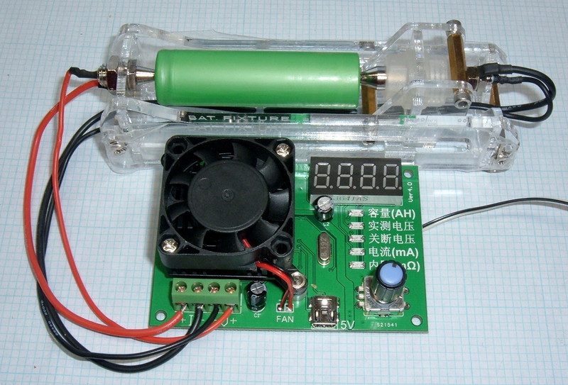
This unit fits the mold! The most obvious feature is the heatsink and fan in the upper left. I’m quite excited that this unit comes with a fan, because a lot of the units get dangerously hot without them (certainly hot enough to leave a mark). There’s a battery connection (4-wire) in the lower left, and a mini USB power connector in the center. I prefer mini USB to micro USB for connections, since the mini connectors seem to last longer in my experience.
Finally, the right half of the board is the user interface. The top is the value display, the LEDs indicate which value is being shown, and the knob at the bottom is used to control the unit. You can twist the knob and push it down!

On the back, there’s the manufacturer (“Shunda Electronic”), and various integrated circuits, plus the usual mix of passive components. I don’t like that my particular unit didn’t come with standoffs to support it, but it does seem that most of the kits on the market now have these included. You can see the higher current traces running around the back.

Zooming in on the interesting section, there are a few things worth mentioning.
The upper left corner is the shunt resistor (made of 4 resistors in parallel). Standard resistor decoding indicates that “R330” decodes to a 0.33Ω resistor. Four of these in parallel work out to a total shunt resistance of 0.0825Ω. At the maximum current of 3.5A, this means a voltage over the shunt of 0.29V and a total power dissipation of 1W (or 0.25W per resistor). That’s reasonable enough, and these are nicely thermally coupled to a large ground plane.
On the lower left is a TM1620 chip. This is a Chinese chip for driving 7 segment displays - like the one on the other side.
The LM324 in the upper right should be familiar to those who have wasted a lot of time on small electronics. This is a quad op-amp. It appears to be trying to look like a Texas Instruments chip, though I seriously doubt it’s a legit one (if there’s not a fake version, you haven’t really made it as a simple IC maker).
Finally, in the center of the board, the brains of the operation - a STC 12C5608AD microcontroller! This is a high performance implementation of the old Intel MCS-51/8051 instruction set. You can look through the datasheet for this chip if you’d like, but this particular version has 8kb of flash (for program storage), a whopping 768 bytes of SRAM, and 4kb of EEPROM (writable storage for persistent data). Plus, importantly, a 10-bit A/D (analog to digital) converter - ideal for turning voltages into binary data!

Overall build quality is quite good. There’s still some flux on some joints, but I have no complaints for a $15 Chinese tester.
Operating Manual
One of the nice things about this device is that, with a quirk or two, it’s super simple to operate. There aren’t any particularly arcane sequences, and if you don’t recall exactly how to use it, 30 seconds of messing around gets you everything you need again.
Hooking Things Up
You can operate this tester in “2-wire” or “4-wire” mode - and, unlike some other testers, there are no settings to change. It uses what you’ve hooked up.
In 2-wire mode, hook up the load wires to the I+/I- terminals and leave the V+/V- terminals empty. For 4-wire mode, which is needed for internal resistance reporting, add the voltage sense wires to the V+/V- terminals.

I’ll discuss this a bit more later, but be aware that this tester pulls current on the V+/V- wires - they are not just high impedence sense wires! This means that if you use some super tiny 22 gauge wires for the V+/V- hookup, they’re likely to get hot during high current testing. I don’t like this behavior one bit, but it’s how this unit works.
Once you’ve got the battery hooked up, attach a micro USB cable for power and you should see LEDs! It’s worth mentioning that it’s a good idea to hook the cables up before putting a battery in the test fixture, or you might spot weld your battery cables together. Hypothetically.
Overview of Controls
The user interface here is pretty simple - there’s a knob you can rotate and push down. There are 5 LEDs that indicate what setting you’re on. Rotating the knob changes the value, if applicable. There’s a 4 digit 7 segment display. That’s about it!
Some of the indicators have Roman letters, some don’t. But, going down from top to bottom:
- AH. If this LED is lit, you’re looking at the total amp-hours (to the mAh precision, with the decimal point). Presumably, the decimal changes as the value changes, though I’ve not tested any batteries large enough for this to happen. Pressing down on the knob with this selected starts Mode 1 testing.
- Current battery voltage. This shows the voltage of the battery connected. If there’s no testing going on, this should correlate quite accurately to the actual battery voltage. In Mode 1 testing, this shows the open circuit voltage (with the battery temporarily unloaded). In Mode 2 testing, this shows the under load voltage. Pressing down on the knob with this selected starts Mode 2 testing.
- Termination voltage. This specifies the termination voltage (relative to the currently reported voltage - it goes against the reported voltage based on the Mode 1/2 setting). To set this, press down on the knob. You’ll see all 5 LEDs light up, with the center LED flashing. Twiddle the knob up and down to set the voltage between 0.90V and 12.0V in 0.05V steps (above 10V, you’ll have to turn the knob twice to change the setting by 0.1V). When you’re done, press the knob again to save the setting.
- Discharge current in mA. This specifies the current to pull from the battery. Again, push the knob to set the current. You can select from 50mA to 3500mA in steps of 50mA (from 50-500mA) or 100mA (above 500mA).
- Measured internal resistance in mΩ. When a test is running, this setting shows the calculated internal resistance of the battery. This only is populated in Mode 1 testing with a 4 wire battery harness properly connected.
When testing is underway, the LED indicator is flashing, and the various positions will show the corresponding value. During testing, you can freely change the termination voltage and testing amps by selecting them and pushing the knob down - changes take effect immediately.
To stop testing, simply press the knob while the AH or current voltage is selected.
When testing is terminated by hitting the termination voltage, the status LED will select the top option (AH), and the calculated AH capacity will flicker on the display.
To clear the AH value, hold the knob down for 3 seconds while not running a test. This should reset the accumulated AH. Alternately, you can disconnect and reconnect the USB plug. The termination voltage and current setting are saved over a power cycle, but this clears the Ah value.
Testing Modes
There are two testing modes, depending on what sort of device you’re dealing with - “Mode 1” and “Mode 2” in the documentation. You enter Mode 1 by tapping the selector on the top indicator (AH), and Mode 2 by tapping on the second indictor (current voltage).
They both test loads, but Mode 1 terminates voltage based on open circuit voltage (the unloaded battery voltage), while Mode 2 terminate based on the under load voltage. Since battery voltage will sag under load, devices often terminate discharge based on the open circuit voltage - and this does get you a bit more capacity, so is how batteries are usually measured. Mode 2 is better for things like USB power banks or voltage converters that don’t exhibit battery-like voltage sag and may be upset by really rapid transients in load (or may not keep up with the load spike after the voltage check, leading to early test termination).
If you don’t have any specific requirements, use Mode 1 for batteries and Mode 2 for anything with power electronics in the way. You can use Mode 2 for batteries as well, if you have a particularly saggy battery, but the test will end earlier for a given termination voltage.
Power Limits
This unit is limited to about 16W, and it does a great job of self protection on that front. If the voltage is over about 5V (where the 3.5A current limit would exceed 16W), trying to set a higher current simply doesn’t work - it rolls over to a lower setting. If you get smart, and use a variable power supply to start it at 3.5A and then ramp the voltage up, the current will back off as you bring the voltage up. So, nice job here - I see no obvious way to exceed the power limits, which is exactly how it should be. Don’t worry about this limit!
Accuracy
To test the accuracy, I pulled out my BK Precision 5491B and let it warm up for a while. This is a new bit of lab equipment for my blog reviews, but it’s a good bit more accurate than other devices I own. I’ve upgraded some of my lab equipment in the past six months, and you’ll see the other upgrade next week!

My first test (because it’s the most important) is the current accuracy. I ran all the current through the ammeter, and recorded the actual current for various settings on the device. What I found is that it’s awful below about 500mA, and then settles in quite accurately. At the 50mA setting, it’s only actually letting 36.5mA go through, which is absurdly bad - that’s 25% low. Around 500mA it comes inside a 1.2% tolerance window and remains there through the rest of the current values. This isn’t a big deal for normal test currents, but I’m not sure why it’s so bad at the low end. It’s surprisingly accurate everywhere else.

I did the same thing with voltage - ran a bunch of voltages through it from my variable power supply, and recorded both the actual voltage (as per the 5491B) and the reported voltage (to three decimal places - because it reports that, just not on the 7 segment display). Then I calculated out the percent error and charted it. It’s off at the very bottom end again (not nearly as bad as current), but in any range you’d likely care about it for lithium batteries, it’s quite accurate (1% from 2V through 14V). So, pretty good, but I really do wish they’d work out the bottom end errors on this unit. it’s accurate where it counts, at least.

Finally, I tested capacity at a few settings with some other units I’m familiar with.
I tested some batteries with the TEC-06, as well as with my ZB206+, which is my go-to battery tester.
For a pair of Eneloop Pro AAs (awesome, awesome NiMH batteries, and low enough self discharge to be useful in things like remotes and wireless mice), at 1.5A, with a termination voltage of 1.0V:
- ZB206+: 2297mAh, 43mΩ IR
- TEC-06: 2369mAh, 45-55mΩ
That’s a difference of 3%, on two different batteries, which is well within the bounds of what I consider acceptable. The TEC-06 internal resistance reading tends to bounce around a lot more than the ZB206+, though - it will bounce through a range of about 10mΩ, when the ZB206 is rock solid within typically 2-3 mΩ. They’re both in the same ballpark, though.
For my next test, which is more representative of how these are more likely to be used, I tested some brand new Panasonic NCR18650Bs, at both 1.0A and 2.5A (the highest I could test on both testers). Internal resistance readings are from the end of discharge. I used Mode 1 testing with the TEC-06.
At 1.0A:
- ZB206+: 3142mAh, 45mΩ
- TEC-06: 3144mAh, 54mΩ
At 2.5A:
- ZB206+: 2986mAh, 43mΩ
- TEC-06: 3081mAh, 46mΩ
At 1.0A, they’re identical in capacity. At 2.5A, they’re about 3% apart - and watching the end of the test, it was obvious that the ZB206+ terminated a bit earlier because it uses under load voltage. I’m betting if I used Mode 2, the results would be right on the money as well.
So, absolutely within the ballpark of other units I consider pretty good.
The Software
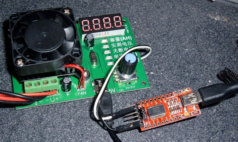
Some of these units (not the ones on eBay, it seems) are sold with a serial interface capability. Pretty fancy! And you can even find the software for it. It’s in Chinese, of course - so I wouldn’t run it on anything I particularly cared about. Virtual machines and all.
But, if you want it, and happen to have the serial version, you can find a download here (if this stops working, let me know and I can re-upload a copy somewhere).
It makes a nice graph (if you let it run), and shows you the current settings. Spiffy! I expect it would look better I had the language pack for it and actually read Chinese… it’s usable, though.

Of course, if you don’t have the serial version, this isn’t seem terribly useful - or is it? You’ll just have to check out the next post for details on that. I might have found a tip to get a serial datastream off the non-serial models, and just maybe reverse engineered the serial protocol. Come back next week if this is exciting to you.
Quirks of Current
There’s a convention for how you engineer something like this for a 4-wire connection. You draw the current on the I+/I- pins, and the V+/V- pins are high impedance voltage sense only pins. M’kay?
This unit doesn’t do that. While testing, the vast majority of the time is spent with both the I pins and the V pins drawing current, more or less in proportion to the wire resistance of the sense leads.
When I was analyzing this unit, this particular behavior drove me batty for about 2 hours. I couldn’t figure out why the measured current (on the I+/- pins, of course) didn’t resemble the set current - and, worse, why the error changed depending on the battery I used, and the wires I used to hook stuff up.
Well, it turns out, the different batteries I was using to test don’t all have perfectly smooth ends (some are pulls from random devices), so the current and voltage sense pins didn’t always seat perfectly. And, with other testing, I used different wire gauges to hook stuff up - so the resistance ratio changed, and I’d measure different current depending on how I had stuff hooked up.
Once I understood this, this is actually quite good in terms of current accuracy at normal loads. But this is a case of something that took me an awful long time to figure out, because I assumed one convention and that was not the case. There’s nothing wrong with what they’re doing here, and it probably leads to cooler wires on average, but it’s just weird, and not at all normal.
Video Reviews and Current Quirks
That previous section leads smoothly into a discussion of why I don’t do video reviews and video teardowns, despite occasional requests along those lines. I genuinely spent most of my time fiddling with this device under the impression that it was a comically inaccurate lying piece of garbage, because I had all 4 wires hooked up, and was only measuring current on the I+/- wires. It was comically bad, and quite inconsistent. Well, had I been doing a live video review, that would have been a problem, because I was wrong. It’s not comically inaccurate. It’s pretty dead on. I just had some false assumptions about how it handled things.
I get that a lot of people like the videos of “This is rubbish,” and if you do, great. There are plenty of channels that cater to that. I just don’t want to do that unless something actually is junk, and sometimes my impressions are entirely wrong about a product.
My goal is to provide a useful manual, a useful analysis of how good something is, and to do this in a form I enjoy, which is text and photos. I can search it, I can skim it, and I’m not forced to wade through 45 minutes of someone’s chatter and muddling around in order to figure out what actually matters. I’ll share some of the muddling around if it’s interesting (as is the case here), but if you don’t care, just skip the section. It’s up to you, not up to me!
Final Thoughts
As long as you stay away from the super low currents where accuracy is suspect (at least on mine), this is a great tester. I really like that it comes with a fan - this is a big deal for handling higher power limits, and it means I don’t need an external fan to keep the tester from getting too hot (like I do with the ZB206+).
I don’t like how badly the internal resistance reading jumps around. That’s a problem - it should be able to come up with consistent numbers. But it does get you into the proper range, and that’s good enough for a lot of testing. Plus, you get continuous internal resistance reading during testing, which is useful enough - just average over the last 10-15 seconds and you should get something consistent enough.
That this tester supports 3.5A out of a single lithium cell, and can deal with the heat, is exciting. My former go-to tester, the ZB206+, only handles 2.6A - but the heatsink gets incredibly hot without external cooling. This handles it far better, and is far less likely to burn you if you touch the heatsink by mistake.
The only real loss is that the ZB206+ will show you watt-hours as well as amp-hours - that’s useful information, and I’d love to see a TEC-07 that had this feature, but it’s really not critical for rating batteries. You can get the idea with internal resistance values and amp-hours.
With what I’ve seen, I think this is my new favorite battery tester. It does what I want, the interface is easy to use, it doesn’t get overly hot, and it even has serial output capability. What more can you ask for?
As hinted throughout this post, I’ve worked out the details on the serial protocol, as well as how to extract that from the non-serial-enabled units. I cover that in next week’s post!
Book Review #1
As promised last week, I want to start reviewing some books every now and then - the whole distraction reduction thing is really good at opening up time for reading. I still love my Kobo - it swallows just about everything, including de-DRM’d Kindle files, and makes a great reading platform. So, let’s start 2018’s book reviews out with something interesting!
Lights Out: A Cyberattack, A Nation Unprepared, Surviving the Aftermath (Ted Koppel)
This isn’t a particularly amazing book, but it’s short, and has some useful information in it. Ted Koppel (the Nightline anchor, for those who remember that) dives into both the feasibility of a catastrophic cyber-attack on the United States power grid (likely), and the likely responses to it (poor). The book then spends the second half looking at various regions of the United States and how they generally prepare for emergencies, and how they would likely fare. This book has, by far, the best description of the Mormon/LDS preparedness systems I’ve ever seen in print, and is worth it for that alone. If you pay attention to how well our nation is prepared for any sort of “cyber action,” there’s not much new in here, but the interviews with people about how various regions would likely handle it are worth the read.
Comments
Comments are handled on my Discourse forum - you'll need to create an account there to post comments.If you've found this post useful, insightful, or informative, why not support me on Ko-fi? And if you'd like to be notified of new posts (I post every two weeks), you can follow my blog via email! Of course, if you like RSS, I support that too.


