
When I’m reviewing hardware, I always look around to see what I can find about it on the internet (beyond the 500 pages selling some version or another). For the TEC-06 I reviewed last week, I came across a helpful hint on BangGood about how to make the non-serial version of the hardware a serial-enabled version - along with some links to the software that talks to it. Given that (and the tools in my office), I set out to reverse engineer the serial protocol, because, well, it sounded fun. And a serial enabled battery tester is a handy thing to have around, if you want to do some data analysis or logging.

With a New Year’s Day afternoon, I sat down and started hammering on the problem. A few hours later, it was solved. I’ve got the serial protocol totally worked out, spent a bunch of time wrapping my head around some bizarre issues, and figured I’d share the process here, for those who want to undertake some similar proceedings in the future. I even published the software to talk to it from Linux!
So, if you want to read about some serial protocol reverse engineering starting from not very much, read on!
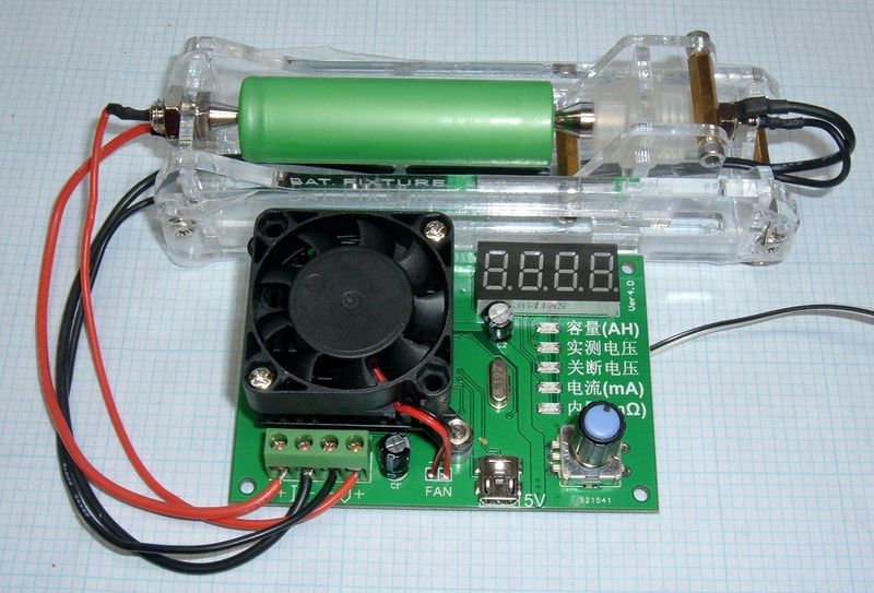
The TEC-06 Battery Tester
I reviewed this unit in detail last week, but in a nutshell, this is a semiconductor-based battery tester. It uses a power transistor as a variable load to dissipate a steady current out of a battery while it discharges, and it measures the capacity. This is quite useful for testing batteries, since this is how one normally tests them. The TEC-06 supports up to 15V input voltage, up to 3.5A of discharge current (as long as you stay below 16W), and has a nice mode for testing power banks and other devices that don’t behave like a battery.
I quite like it, though I wish it had watt-hour capacity as well. However, with the data coming out, I could probably calculate watt-hours if I want (at least in the under-load voltage mode - it wouldn’t be quite right to use the open circuit voltage to calculate watt-hours).

Reversing the Protocol for Fun and Profit
Why bother reverse engineering the serial protocol on something goofy like this? There’s software that works for it (you can even find a copy, which is rare), and the hardware hacks are easy enough to plumb into the official software (as long as you’ve got a serial port run into Windows, the real software works fine). Why go through the full reverse engineering process? Several reasons:
- The software is Windows-only, and is unlikely to remain supported when Windows changes anything. If you want to, say, use this on Linux - good luck. But serial protocols are simple and usually pretty easy to reverse. Making this gizmo talk to a Linux box is convenient.
- I don’t know about you, but I don’t exactly trust Chinese software packages. I’d rather use my own datalogging software if it’s just dealing with data over serial.
- But, mostly, it’s the challenge. This is a puzzle. It requires writing custom code (at least, it’s a lot easier if you write custom code), and I usually learn a lot in the process of doing something silly like this. I learned a good bit on this project, had an excuse to pull out my voltmeter and oscilloscope, and basically spent an enjoyable afternoon heads down in virtual machines, voltmeters, power supplies, and raw serial data. Yes, I do find that enjoyable, though I recognize not everyone does.
Beyond just the challenge, I find it useful to understand how these devices work. I’ve found an awful lot of similarities between different devices by the same company over time, and working out one, in detail, is often useful in understanding other devices.
But, really, you’re either going to understand this sort of use of an afternoon, or you’re not. If you don’t, that’s fine. If you do, well, jump on in!
Verifying Serial Output (and Checking Baud)
Before going any further, it’s worth verifying that there’s something that looks like serial data hanging out on the (tacked on) port. The tip from BangGood suggested that pin 3 on the MCU might be a good place to check for serial. Before wasting my time, it’s worth seeing if this suggestion is even plausible. If pin 3 is a ground or something, well, not much use in going further.
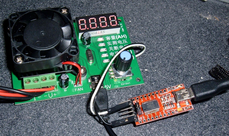
The main chip is a STC 12C5608AD - with an easily found datasheet. And, indeed, on the pinout for the 20 pin package this tester uses, pin 3 looks pretty promising! A Tx (transmit) pin for, presumably, an onboard serial UART!

I attached two wires to the chip - one to the Tx pin, one to ground. If these look like jumpers with an end stripped off, that’s because you’re exactly right.

With a connection in place, the next step is to look for something that looks like serial. Just because there’s a transmit pin doesn’t mean there’s any data on it, of course. This is explicitly the non-serial version of this device, and it’s possible (but highly unlikely) that the firmware is different between the serial and non-serial versions.
For quick checks like this, I normally whip out my handy DSO138 oscilloscope. Mine is USB powered for convenience (they run on 9V so I have a little boost converter on the back), and if something goes wrong, I’d rather fry a $20 scope than a more expensive one. With a bit of fiddling around (setting proper trigger levels with this thing is far from easy), I found something on the wires that looked very much like a TTL serial protocol (high and low voltages to mark data). This shows promise!

Unfortunately, this scope isn’t good enough to give me anything particularly useful in terms of detailed baud rate. I know it’s above 100k baud, and presume 115200 baud, but that’s about as close as I can get. This scope really isn’t useful for precision work at this frequency - which is perfectly fine. It’s a $20 single channel oscilloscope good to 200kHz or so. That’s more than enough value to justify having one around.
It’s time to pull out the proper scope. A while back, I purchased a somewhat nicer scope than my DSO138. It’s a Rigol, it’s a 4 channel, 100MHz scope, and it does nice screenshots, CSV export of data, and a bunch of other fun stuff I’ll be making use of when I have reason to. This is one of those “precision instruments” that I can use to verify other things are accurate (or laugh at how comically bad they are - either way). Those of you who have read quite far back may recall that I’ve used a comically ancient scope in some posts, and I still have that, but I’ve also upgraded. Significantly.
So, here you go - the first of hopefully many oscilloscope screenshots on this blog going forward! This is most definitely a TTL serial protocol on the wire. And with my new scope, I can do some fancy measuring to find out just how fast it clocks along! Notice how much cleaner the signal is on this scope vs the DSO138.

There are various automatic tools I can use, but the easiest way to measure something like baud rate on an unknown signal is to zoom in on the smallest section you can find and use the cursors. “Box the signal” and you can find both the voltage and the time of each symbol. The Rigol, helpfully, shows me the “1/dX” frequency calculation at the bottom (exactly what I want). And I get a baud rate of 128.2kHz. Plus a peak to peak voltage of 4.2V (so I’ll call it 5V serial, not that it matters for receive - 3.3V and 5V signaling are both high past 2.5V or so, but you shouldn’t attach this to a 3.3V device without some voltage clamping).
For the record, a normal serial baud rate in this range here is 115200 baud. 128k baud, give or take, is not a normal one. But the scope is pretty clear on it, and I do trust this scope.

The Windows Software and Serial Sniffing
Virtual machines are good. Seriously, virtual machines are awesome and I wish they’d existed when I was in college. They’re great for, say, installing sketchy Chinese software that needs admin rights to run (it couldn’t talk to the serial port without it, though there’s probably a way to resolve that if one cares). Hopefully they don’t bundle a hypervisor escape with them into a different host platform…
With confirmation from the scope that I’ve got a TTL serial signal, I set about running this signal into a computer. If you’ve read my blog for a while, you might recognize my FT232RL adapters. These came with the fake FTDI chips, and I did a bit of surface mount rework to replace them with legitimate FTDI chips (which actually work at the rated 3M baud). The adapter is set for 5V, not that it matters for receive. After hooking this up, I’d see a flicker of the receive LED once a second, which means it sees something that looks like data!
I found a copy of the software for this bit of hardware (it’s in my github repo if you need a copy), connected my adapter through to the virtual machine, and, astonishingly, the software saw the device! Words cannot express just how amazed I am that this software actually works in this slightly hacked up configuration. But it does make my life easier, since I can actually see how the port is configured instead of having to reverse engineer that, too. The data even matches what’s showing on the little 7 segment display!

With the software running and talking to the device, I fired up a trial of some serial port sniffing software (other perks of virtual machines - snapshots to get rid of stuff like this cleanly). This software showed me the data coming across the port, as well as the port configuration - 128000 baud, 8 data bits, even parity (!), 1 stop bit. I really can’t tell you the last time I saw parity enabled on a serial connection. It’s incredibly rare. But, the scope doesn’t lie. This is a 128000 baud serial connection, weird though that is. However, for microcontrollers, the serial UART is usually clocked at some fraction of the main crystal instead of having a separate serial crystal. With the 8.192MHz crystal on this board, 128,000 baud is a serial divisor of 64 - a nice power of 2 that’s easy to deal with in hardware. To get 115200 baud off that crystal, the divisor is 71.1 - far less nice to work with (and actually impossible for a microcontroller - you’d use 71 and rely on being “pretty close”).

This certainly saved me a bunch of time - I could verify the port settings and also see the data coming across the wire to verify that what my setup received more or less matched the actual data. If I didn’t have this, I certainly could have worked out the settings from the scope traces, but it would have taken me a lot longer. This baud rate is close enough to 115200 that I probably would have spent a long while at 115200,8,N,1 before trying something different when it continued to make no sense.
Linux, FTDI, and Weird Baud Rates
At this point, I moved over to Linux. I’m a whole lot more comfortable hacking up code in Linux, I have Linux development VMs, and that’s just where I do my technical work. I write most of my test code and analysis code in C or C++, depending on the project. I know it’s popular to hack up something like this in Python, but I just don’t like Python, and I’m good at C.
The normal way to set serial port baud rates in Linux is the stty program. This doesn’t let you set weird serial baud rates, though. Nor does the standard C termios interface to configuring the serial port. Those set PC baud rates - 9600, 38400, 115200, etc.
Skipping over an hour and change of head scratching and research, the summary is that, to set a custom baud rate (at least on a FTDI device), you configure a divisor in one of the advanced configuration structures, then set the baud rate to 38400 baud via the standard configuration interface. If you’ve set your flags and divisors properly, instead of 38400 baud, you get your custom configured baud. Yes, this sounds insane. Yes, this is how it works. It likely traces back to some decision or other made in the 1970s on a mainframe.
If you listen to the device configured for 115200 baud, you’ll get a data stream of what looks like valid data - but it’s not. I could verify this against the sniffer from Windows, and also against the serial trace from the scope. It really is 128000 baud, and that is really a pain to configure. The source is commented, for those who are dealing with this, but I won’t subject most of my readers to the gory details - it’s not useful unless you find yourself configuring a port for generally unsupported baud rates.
I will say, however, that when dealing with raw binary data over a serial port in Linux, it’s vital to understand how the port is configured, and to configure it properly for raw binary data. There are plenty of in-band signals for serial (software flow control being the usual offender), and ways to configure the port that also swallow or translate characters (converting ‘\r’ to ‘\n’ or the other way, or ignoring one of those). If you don’t configure the port properly, certain values get mutated or go missing. Again, check the source for how to avoid this, but it’s a serious gotcha when dealing with binary data over serial ports. The default configurations assume line based ASCII (CR or LF terminated), and don’t work at all properly for full range binary data.
Starting the Analysis
With everything finally configured so that I could read the proper data in Linux, I crafted a bit of code to read data from the serial port, align it, and print it to the console. A really handy technique for something like this is to highlight data that changes from row to row. I keep the previous row in an array, and if the data has changed, I reverse the text on the changed bytes in the new row. This makes it super easy to see what’s changing when you sweep voltages, or play with settings. It’s a great way to identify what metric is plumbed to what data bytes, even if you can’t see the data relationship immediately. I’m fiddling with the termination voltage here.

Fairly rapidly, I worked out that the first two bytes and the last byte never changed. These are markers of some variety - and 0xaa is a pretty common marker, because 0xaa, in binary, is 10101010 - the same marker I saw at the start of the message on the scope. If you aren’t getting this symbol, something is wrong with your baud configuration.
The remaining bytes changed based on the parameters on the tester. Working out the correlations:
- Bytes 2-3 change with the current set value.
- Bytes 4-5 change with the battery voltage.
- Bytes 6-7 change with the termination voltage.
- Bytes 8, 9, and 10 tick up with the mAh counter.
- Bytes 11-12 change with the measured internal resistance.
However, with the exception of the termination voltage (which is just the value in mV), the value-to-observed-data algorithm wasn’t obvious. That was going to take more work.
Working Out the Values
Presumably, there’s some easy to implement way of converting the observed hex values on the wire to the actual numeric value shown on the 7 segment display (and in the app). I don’t expect a device of this complexity to use encryption or anything else (I’m stunned it even uses parity), so there should be an easy way to convert the values. However, it wasn’t instantly obvious.
The “termination voltage” value was easy. Those two bytes correspond to the termination value in mV - byte 6 is the high 8 bits, byte 7 is the low 8 bits. This gave me a good clue that the actual values were likely present, with some minor tweaks, for the other values. You don’t have one value in plaintext and the rest heavily obfuscated unless you’re just trolling, and I don’t think Chinese hardware vendors have the time to do that. The “mAh” field is also directly mapped like this.
Other values were generally doing sane things - the higher I had a value set on the 7 segment display, the higher it showed in the data scroll, but the translation wasn’t straightforward. I spent some time working on the concept of a scaling factor (0.8, 0.67, etc) for a while, since that seemed promising, but the factor wasn’t constant. It didn’t seem like a good fit for a device like this, either. Little microcontrollers are really bad at floating point math.
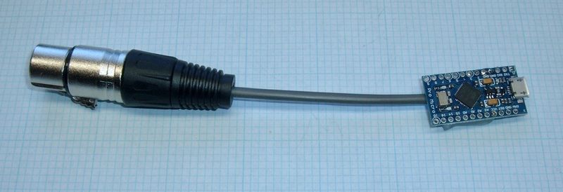
Eventually, I decided to go after the battery voltage value. I had some values that didn’t quite make sense, and I had a the value for 0V (0x200 on the wire), but I didn’t have enough data points to fit. Enter my handy dandy buck converter, which is actually also a review in progress. This gizmo is, for my current needs, a perfectly good variable voltage source. I’ll be talking about it in other posts, but it’s really handy. Yes, there’s an Arduino and serial board attached to it, and, yes, that’s part of a future post.

With this attached, I could vary the voltage in 0.01V steps and see how the data changed. The zero volts value on the wire was 0x200, and that started changing around 0.02V - so there’s no large null region at the bottom. I ran the voltage up in increments, noting the value at each step, and converting to decimal (with the offset from the base). The 3.00V reading confused me at first, then I remembered about the CR (0xd) to NL (0xa) remapping and removed that. A pattern emerged!
0.00V -> 0x200 (512, 0)
0.10V -> 0x24e (590, 78)
0.50V -> 0x3e3 (995, 483)
1.00V -> 0x5d6 (1494, 982)
2.00V -> 0x9c6 (2502, 1990)
3.00V -> ~0xac1~ 0xdc1 (3521, 3009)
4.00V -> 0x11bb (4539, 4027)
The voltage field was (more or less) the measured voltage in mV, offset by 0x200. Why? No clue, but that’s what it was. Byte 4 is the high 8 bits, byte 5 is the low 8 bits, subtract 0x200, and you’ve got the current battery voltage in mV. The display only shows two decimal points, though the software reads more. I actually saw that when I had 4.00V coming in, the display showed me 4.02, which was helpful. Of minor interest, this device truncates reported voltages - 4.027V will show as 4.02V, instead of rounding to 4.03V.
With this bit of a clue into how they did stuff (offset from a base value for unknown reasons), I looked at the other fields with this same eye, and found good results.
I puzzled out the current set and internal resistance fields in much the same way. They’re both a straightforward linear translation of the value with an offset, for reasons I don’t grasp.
The set current is calculated by subtracting 17 from the raw value and multiplying by 10.
The internal resistance is simply offset by 20.
And the mAh value is just directly read out of the three byte data field.
Finally, the last byte is a status byte.
- 01: Running (current is flowing)
- 02: Stopped (the test has not started, or has been manually stopped)
- 03: Completed (the test has stopped due to hitting the termination voltage)
So that’s it!
With all those parts worked out, I can write a bit of code that reads the serial data off the bus, converts it, and emits the values I’d like for my work. Which I’ve done. It even emits CSV.
Notes on the Process
There’s no “right way” to go about a process like this. There’s only “Ways that work” and “Ways that don’t work.” If you get to useful answers, you’ve got a way that works!
I normally set about a process like this with a few sheets of paper. Spreadsheets would probably work as well (and might make the process of finding the offset a bit easier), but when I don’t know what I’m looking for, paper is a great way to organize and diagram things out. I had a copy of the data bytes that I marked up when I found what controlled what, and some small tables of values as I copied them down. I don’t always finish these projects in one day, so working notes are helpful as well.

Often, measuring each individual step and writing the values makes a pattern clear. Starting with 50mA current, the recorded values followed a pattern that became pretty obvious if I worked backwards (and converted to decimal). Why is there an offset of 17? I have no idea, but there certainly is.

Get the Code
If this is actually useful to you, I’ve got a bit of fairly well commented source code available here: tec06.c
It runs on Linux, and while I know it works with (real) FTDI adapters, I can’t promise compatibility with any other serial adapters. If you can get your serial adapter to do 128,000 baud, it should work, but how to set that is left as an exercise to owners of other serial devices. If you do hack on it, let me know and I’m happy to accept updates.
Final Thoughts
Hopefully you find this useful. I’m the only source of the reverse engineered serial protocol for the TEC-06 I know of on the internet (a bit of a niche, it would seem, which is a fun place to play). But having working serial output makes this device a good bit more useful. And it was a fun project! I enjoy excuses to pull out my scope and voltmeter for reviews.
I really like this little gizmo. It’s flexible, it supports higher voltages and amperages than my previous favorite (the ZB206+), and the serial output capability, especially hacked on one that doesn’t have it, is just awesome. If you need a battery tester, I’d suggest this one! It’s less than $15 on eBay!
Comments
Comments are handled on my Discourse forum - you'll need to create an account there to post comments.If you've found this post useful, insightful, or informative, why not support me on Ko-fi? And if you'd like to be notified of new posts (I post every two weeks), you can follow my blog via email! Of course, if you like RSS, I support that too.


