
One of my projects recently has been a helpful little lighting control gadget for our church. We use Proclaim to run the announcements/lyrics/presentation, and FaithLife recently added MIDI support for lighting. Well, our lighting laptop is a clanky old netbook, and we don’t care for it (or having someone sitting there to run it), so I decided to see if I could build an interface from Proclaim’s MIDI output to our DMX stream, with an Arduino.
It turns out, I can! And this little gadget (in various iterations) has been doing a great job running church lights for a few months now! Smooth fades, various scenes, and automatically changing lighting when countdown timers end.

What’s in it? What makes it tick? How do you build one? Keep reading to find out!
Proclaim - and Church Lighting
*gestures with his pipe* Back in my day, son, we ran lyrics with Keynote! Sometimes, we were forced to use Powerpoint! Those were dark days, they were. Why, once when I was presenting with someone else’s laptop, I even had Norton jerkily slide up an antivirus renewal notification over a presentation during the middle of a serious part of a Tom Short sermon! Full screen presentation? Didn’t matter. Norton was more important. We used black desktop backgrounds and black fade in/fade out transitions on all the decks so we could load the next file while the band was transitioning, and we liked it that way! Whippersnappers and their all-in-one integrated software with band confidence monitors. Why, in my day, the band would sing something that had nothing to do with the lyrics on screen, because they couldn’t see the screen! We’d update the lyrics so they’d be correct to what the band was singing next time, and then keep two copies in case the backup band was playing! Kids these days…
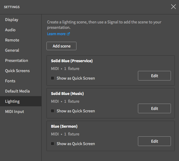
Or something along those lines. In case you’re wondering, every bit of that is true. Except I do appreciate the all-in-one presentation software. Proclaim is what I’d call “Church Multimedia Software.” It handles a properly impressive amount of the assorted things in the audio/visual category of church production. It lets you loop announcement slides before the service, run countdown timers, show confidence slides (lyrics or sermon notes where the band/pastor can see them), display lyrics with static or motion background, play videos, record sermons, and quite a few other things I don’t even know about. And, recently, they added support for lighting control. Somewhat weird control, certainly, but control.
The lighting control they added is the ability to specify lighting scenes, associate one or more MIDI notes/control codes with each scene, and then attach these scenes to particular slides (I call them an entry action - they apply when the slide becomes the current slide, which does mean you can’t skip over slides with lighting attached if you want it to work).

Stage lighting runs on DMX. Ours is all the cheap stuff that runs with the not-approved-for-DMX 3 pin XLR connector, but Donnor makes wireless DMX gizmos on 3 pin, and it is really handy being able to just grab an XLR cable from the sound cart when you need to extend something. I understand the intent of having a different cable so people didn’t randomly connect DMX to the sound system, but I’ve never seen that happen, and the cable commonality is so, so convenient.
Our existing system for running lights involved a little netbook and some software. It worked, but it wasn’t ideal, it didn’t allow much in the way of dynamic lights (tied to the music or sermon), and we simply didn’t make good use of the lighting we had - services were generally static lighting throughout the whole service. With some recent changes in our tech table layout, there wasn’t even room for a person to sit at the laptop without being really, really cozy. The software could do all that stuff, but it just didn’t mesh with how we ran the service.
I set out to build a device that lets us do dynamic lighting easily, reliably, flexibly, and, ideally, without me having to write new code regularly! If the pastors can create new lighting scenes on a whim, even better.
MIDI In, DMX Out
MIDI is fundamentally just a well defined serial protocol. It’s a 31250 baud serial protocol with defined command messages, and a defined way of passing data after these messages.
Proclaim speaks MIDI - it will emit MIDI messages to the specified output device, which can then send it out as serial or do something else. You can send three message types - Note On, Note Off, Control Change (and, in a very recent version, the somewhat less useful Program Change - it only has one data byte). You can direct these messages to all 16 channels. And, you can set both the note and velocity (or corresponding 7 bit data fields) for all three message types (MIDI data is 7 bit, because if the high bit is set, it’s a command). Three commands, 16 channels, and a pair of 128 value data fields. This means you can send 786432 unique commands. I’d say that ought to be enough scenes for most churches, but I’m sure someone would prove me wrong. However, I don’t think 700k scenes is practical to manage in Proclaim - the interface just isn’t suited to that. And I’m certain that my device won’t store that many scenes.

On the output side, DMX is the standard lighting control protocol (for non-critical systems - it’s not suited to pyrotechnics or rigging). This is also a serial protocol (seriously, anything that actually interfaces with the real world talks serial at some level), clocked at 250,000 baud. It sends a more or less continuous data stream out, specifying the lighting level (8 bits - so a value of 0-255) for up to 512 channels (though you can use less). DMX channel 0 is not a valid channel for lighting - that’s reserved (and I make use of this).
Typically, a dimmer for white lights (house lights, spots, floods) will use a single DMX channel, and multicolor lights (most multicolor lights now are made of RGB LEDs) will use at least 3 sequential channels (red, green, blue). Most of the RGB lights out there can be configured to use more channels to enable features like strobing, or a separate grand master for the fixture, but they’ll normally have a sequence of 3 channels controlling red, green, and blue (normally in that order) channel brightness.
There’s a catch, though (all good projects have one). DMX is a protocol running on top of RS-485 - which uses differential signaling. This means that there are two data lines (and a ground), but they oscillate relative to each other. To transmit a 0, one line is low and the other is high. To transmit a 1, the two lines swap. This is a much more robust signaling protocol than normal serial, because common mode noise cancels out at the receiver - so in an electrically noisy stage environment, you’ll get a cleaner signal through. But, an Arduino cannot natively output a differential signal.
Design Concept & Details
At a high level, the concept is very simple: “Build a standalone device that takes the MIDI signals from Proclaim and uses them to control the lights.” Making it useful, though, requires a bit more work - and making it generally useful to other people requires even more.
Proclaim can emit a sequence of MIDI signals for each lighting scene - you can add multiple notes to each scene, and it will hammer them out quite quickly (roughly one command per millisecond - 31.5 line changes per millisecond, with about 30 bits required to send a command once you include the start and end bits). Being able to emit multiple commands per scene opens up a few options, several of which I’ve implemented.
An important feature, to me, is the ability to do smooth fades between lighting scenes - with configurable time windows for the fade. I want to be able to do everything from an instant snap to a slow lighting fade that takes a minute or longer. Realistically, most lighting fades are in the 3-5 second range, but flexibility is good. Sometimes subtle and slow lighting changes are perfect for mood setting, and sometimes, yes, you want to get people’s attention with a sudden change.
The highest level approach is to pair a single note to an entire lighting scene - one note sets all the fixtures to some preset value or another, and lets you fade between them. This requires a good bit of up front programming, and isn’t something easily changed on a Sunday morning during the setup time. However, for churches not using many fixtures (ours included), this works nicely.
The next level down I support is a “fixture mode.” This requires configuring fixtures in the source code, and configuring color combinations for the RGB lights, but it doesn’t require specifying scenes up front - they are built, piece by piece, by multiple notes coming out of Proclaim. There are (currently) two supported fixture types for this mode - a single channel mode for white lights (spots, floods, congregation lights, etc), and an RGB mode for RGB fixtures. Once these are configured in the code, you can set whatever combinations you can dream up!
Finally, because I wanted a mode that works “out of the box” with no programming needed, I support a raw DMX mode. This allows setting any of the first 128 DMX channels to any brightness (the MIDI data value of 0-127 is scaled to the DMX range of 0-255). Because this may involve many commands to many fixtures, this mode requires a “go” command at the end of setting all the new values - and this is what I use DMX channel 0 for. Instead of setting a channel to a value, channel 0 sets the fade time for all the channels and completes the command.
I also support setting “fixed channels” in the code. In some cases, fixtures will have channels that just need to be set to a value, regardless of what else you do. We have some RGB fixtures that need a mode channel set (so we can control the rest of it), and have a grand master channel that we leave set to 255. There’s no reason to set these manually if they don’t change, so I have support for setting these on power-on. You can override them with the DMX channel mode if needed, but I don’t expect people will do that particularly often.
Development Based Features
No project like this will anticipate everything that can happen in a production environment, and on the very first Sunday of using the controller, during the first 10 minutes of operation, I discovered that my initial implementation led to a controller that reliably blacked out all the lights if someone messed around with the USB devices on the laptop to add a microphone.
I’d set the board to black out all the lights on reset. This seemed a reasonable default state - set the lights to black, bring up the first scene, and everything gracefully fades up. What actually happened is that when someone inserted or removed a USB device, the controller got reset, and blacked all the lights out without warning (and as Proclaim won’t emit new notes until the next slide with lighting signals attached, they remain black). Not ideal. I subsequently devised a system that would store light scenes (after the fade) to the non-volatile EEPROM on the chip, and the system restores from that state before bringing the DMX output online. No glitches, even if you randomly unplug and plug devices from the computer.
Hardware: The Prototype
The Arduino ecosystem is just awesome for hacking together prototypes for something like this. Though a bit more research would have saved me some time and money. I’ve got an Arduino with two shields on it - one MIDI, one DMX, an external MIDI adapter, and a spare USB hub because the presentation computer only had one free USB port with the normal configuration.

Like most of my other parts bins, these parts come straight from eBay - mostly shipped from China, because for the cost of one unit on Amazon, I can get 5 out of China if I’m willing to wait a few weeks. I normally order a few of a board at a time, and am building up a nice collection of spare parts and boards. Plus, I keep some prototype shields around, which are great for rapid hacking together of random parts if I find the need.
My Arduino is just one of the standard Chinese Uno clones I use. I’ve got a few genuine Arduino boards, but most of my development is on the Chinese boards with the CH serial adapter - they’re cheap enough that I usually don’t bother with the various protections in my circuits, because if I fry a board, it’s cheap enough to just replace it. I’ve not fried a board yet, for what it’s worth…

My DMX shield is an old TinkerKit DMX shield (less than $10 on eBay). TinkerKit doesn’t seem to be around anymore, but you can still find the hardware pretty cheap if you want a basic DMX shield. You’ll want to use the DMXMaster library (old but still works great), the schematic is still online for reference, but, basically, bang out a DMX signal on pin 3 and you’re good. I didn’t bother soldering the 5 pin DMX connectors on the left, since I had to interface with three-pin XLR connectors anyway.

The MIDI shield is the cheap Arduino MIDI shield you can find on eBay for about $10. It’s a 6N138 optical isolator and a few MIDI sockets (that may look oddly similar to AT keyboard connectors, if you’re that old). Cheap, simple, and ties MIDI in/out to the hardware serial UART (pins 0 and 1). You’ll need to turn the switch “off” to program the Arduino over serial, and “on” to receive MIDI - if you leave the switch in the “off” position, you won’t receive any MIDI commands. This will drive you nuts at least once.

To stack everything up, since the DMX shield has a high set of connectors, you’ll need some Arduino header extensions. I use these for building proto shields, and also as risers for situations like this. Since the DMX shield has fairly tall connectors, these let the MIDI shield sit on top. Without these, I’d have no way to link all three shields together.

I’ve got a whole drawer of assorted 2.54mm pin headers (0.1”, if you’re curious about that odd sounding size) I make use of, and they’re great to have around. I use them quite frequently on various projects, and while I doubt I have a lifetime supply of these, they’re cheap enough that you shouldn’t ever run short on them. Just order 100 strips or something.

With all that stacked up, I set to work on the code. You can find the code in my Github repo, and it’s fairly well commented, if you want to understand it - I’ll talk about the parts you need to change next week in the “how to use this” post.
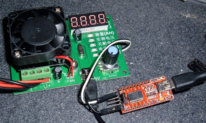
Testing the Prototype
The initial testing involved a few RGB cans I have in my office for some repairs and upgrades (the LEDs on them are acting up, and the power cords are too short). That worked fine, and proved the concept, so the next step was testing with the full setup.

Other than needing to change the MIDI device configured in Proclaim, everything worked - though, as I noted above, it did black out the whole lighting setup a few times while people were messing about with other USB devices. Whoops. Resolved with a bit of EEPROM use (this is a perfect use for the onboard EEPROM).
With that bug resolved, it works quite nicely, and entirely as hoped in production. We ran a month or so on the prototype with no problems beyond forgetting to toggle the switch on the MIDI shield.
Slimming Things Down: The ATmega 32U4
The problem with the prototype stack, though, is that it’s huge. And ugly. And takes up a lot of room on a very small table (one perk of this device is that we don’t need two people sitting shoulder to shoulder running the main laptop and the lighting laptop). Plus, it’s rather expensive - and has a ton of functionality that I simply don’t need. I don’t need MIDI out or thru. I don’t need DMX in. And, really, I don’t even need the serial stage of MIDI - I just need a device that reports to the computer as a MIDI device and has the data. Ideally, I can have a USB port on one end, a DMX port on the other, and a small board in between.
Initially, I assumed I’d need my own custom board to accomplish this. Some sort of USB to MIDI converter at one end, the main processor chip, and then a DMX output device. That was before I dug into what, exactly, the ATmega 32U4 chip was. It’s the chip for the Arduino Leonardo, and also the Arduino Pro Micro.
In a nutshell, it’s an ATmega chip - with onboard USB. And that onboard USB is easily configurable to do an awful lot of cool things, like be a keyboard, a mouse, a joystick, or, in this case, a MIDI endpoint!

The Arduino environment comes with PluggableUSB support, which means that you can add USB functionality to an endpoint at runtime, and it becomes that device to the computer (if you wish to put an evil keyboard device on a coworker’s computer, this sort of functionality is perfect). In this case, I can add a MIDI endpoint and get an “Arduino Micro” MIDI device on my computer. I send notes to that device, and they appear in the microcontroller as fully formed MIDI commands!
If you dig deeper, you can change the name the device reports as, but “Arduino Micro” is unique enough for my needs, and the process to change it is a bit more complex than I felt was useful. It’s not hard, it’s just annoying enough that I don’t care for it. But, if you want to change the name, that should point you in the right direction.
After I get the MIDI commands, I just bang out my TTL DMX signal on pin 3, toss an inverting driver on it for the proper signal, and I’m good! It can’t be that easy - can it?
The Arduino Micro Prototype
Well… actually, yeah, it really is that easy. The MIDIUSB library turns the 32U4 based chips into a MIDI endpoint, and beyond including this library and changing my “Receive MIDI command” function around a bit, the rest of the code works perfectly. It’s such a smooth integration that I can just have a #define at the top of the file that changes between the serial MIDI and USB MIDI - it’s really only one function that changes!
However, the 32U4 still can’t natively output a differential serial signal. It can only output a TTL serial signal (high and low voltages). To convert this to the differential signal that the DMX specification requires, I need a converter chip.
The MAX485 is just such a chip! This is a high speed (2.5Mbit) capable chip designed to do one thing - translate between a differential signal and a TTL signal. It works both ways, though I’m only going to need one of the ways (convert TTL to differential).
Shove a MAX485 in a breadboard next to the Arduino Pro Micro, hook up some jumpers, and… it works! I had to swap the DMX +/- signal wires since I had them backwards at first, but it works!

This is one of the easiest hardware revision changes I’ve made in a project, ever. Rarely do things work this smoothly.
But, this breadboard isn’t much better than the old version, in terms of “looking good.”
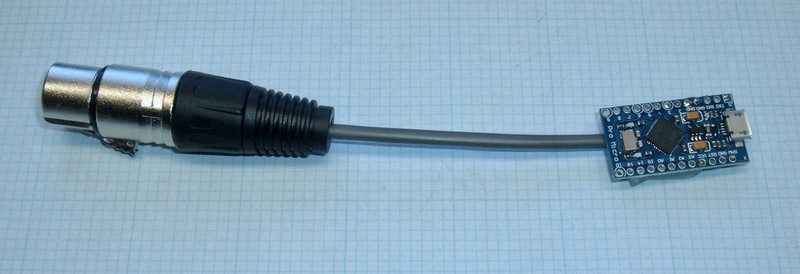
The Production Version
As nice as a breadboard is, it just doesn’t look right in the back of a church service (though, perhaps, better than the old prototype mess). Though, more importantly, it’s not robust against toddlers, and rewiring a breadboard under pressure in the middle of a suddenly dark service just doesn’t sound like my sort of fun.
So, I took the breadboard version, deadbugged up the differential driver IC on the back, and I’ve got my production version!

That’s not very satisfying, is it? And you don’t really expect me to stop with “And then it was done,” do you? Of course not. That’s not my style!
Parts List
To build a production unit, you’ll need the following parts. I got all mine on eBay, because I don’t mind waiting for shipping, and I usually order a bunch of these parts at once for office stock.
- Arduino Pro Micro - 32U4 based. This is the core of the unit, and should run you $6-$8 shipped.
- MAX485 DIP IC. This is the differential driver. Less than $1, though you might want to avoid the super cheap versions - they’re probably fake.
- Female XLR plug. This hooks into your DMX system somewhere - you want one with solder cups, and that should run you around $1-$2.
- Three conductor wire. I don’t list a link to this, as you can find it locally or just rip up some network cable for it. I’m using some 4 conductor security system wire I purchased locally (I have 500’ of the stuff, and it should last me through many, many projects).
- Some random solid core wire for short jumper connections.
Building the Production Version
Of course, you expect build details out of me - and I intend to deliver. Not only build details, but build directions, so if you want something like this, you can build your own! I’m happy to sell you one, but I’d really rather you build your own (or have someone in your church build your own). They’re simple enough to build.
The XLR Connector
Yes, I know, the three pin XLR is explicitly forbidden in the DMX spec. And, you know what? Everyone uses it. I didn’t know DMX was a 5 pin spec until I started this project. Being able to go snag a spare mic cable is very, very useful. In any case, you’ll need a female 3 pin XLR jack.
The wiring diagram is pretty simple. Pin 1 is ground. Pin 2 is Data-. Pin 3 is Data+. On a three pin XLR connector, pin 3 is the center (high) pin - but they should all be labeled.
My wiring color scheme is simple enough. Black is ground. Red (sun/sky) is Data+. Green (grass) is Data-. It’s nothing fancy, but it’s easy for me to remember. I assume through the remainder of this writeup that you’re using my convention here. If you’re using different wire colors, well, convert the colors!
Once this is all soldered, put the connector back together.

Driver IC Pinout and Leg Folding
So, this “MAX485” driver IC? What is it, and how does it get hooked up?
It’s, oddly enough, a RS-485 transceiver. You can check out the datasheet for more details, but this chip takes a TTL signal (serial swinging between 0V and 5V), and converts it to a differential signal out over the wire. It can also receive a RS-485 differential signal and convert it back into a TTL signal for electronics to receive, but that’s of no interest in this project.
Pin 1 is the top left, with pins 1-4 going down the left side, with pins 5-8 coming up the right side. Since this chip only needs to transmit, we can make a few shortcuts in the wiring. The cutout on the chip is the top part, if you’re not sure how to orient a DIP package.
Pin 1, top left, is the receiver output pin. We don’t need to receive anything, so this is NC - no connection.
Pin 2 and 3 control the mode of the chip (transmit, receive, or idle). Pin 2 is Receiver Output enable (inverted) - if this pin is low, RO (pin 1) is enabled. If it’s high, output is disabled. Since we don’t need it, I’m tying it high to disable the output pin. Pin 3 is Driver Output Enable. If this is high, the chip is driving the outputs based on the input signal - this is what I want it to do, so this pin is tied high as well.
Pin 4 is the Driver Input. This is where we stick the TTL signal to be converted.
Pin 5 (lower right) is ground. Tie this to the common ground.
Pins 6 and 7 are the outputs - for the setup I’ve got, DMX+ is pin 6, DMX- is pin 7. If you inverted the input signal, you could swap these and still be fine.
Finally, pin 8 (top right) is Vcc - positive supply. This chip requires 5V, which, conveniently, is what USB outputs, and what my Arduino Micro runs on!

Since this is a deadbug style build, the next step is to fold and cut the legs on the IC.
I cut pin 1 off - no need for it. Pins 2, 3, and 8 are all tied to Vcc, so they fold around to the back (you can see the detail in the next section). The data pin is folded out with the tip down to engage in output 3 of the Arduino. The two DMX pins are folded out so I can easily solder to them. And the ground pin is folded out and down.
How you fold them doesn’t really matter as long as you keep the separate pins separated, and make the connections properly.

Attaching the Deadbug Driver IC
Why do I call this “deadbug” style construction? Because the driver IC, flipped over, looks like a dead bug! “Deadbug” circuit construction consists of (typically) DIP ICs, on their backs, with connections made between them. In this case, since I really only need one additional IC, there’s no point in building a new circuit board for this build. If I needed several new ICs, sure. But one? I can solder that. You can see a bit more detail on how I folded the legs here (the IC is upside down compared to the previous photo, and I don’t have the edge of the data pin folded down here). The three Vcc pins are the important ones to notice. They’re all touching, and will be bonded together with a blob of solder.

I superglued it to the back of the Arduino. If you’ve not worked with the Loctite gel superglue, you’re missing out. These are awesome bottles that are totally worth the $5.
Notice that the top right leg (the data in pin) is looped through pin 3 on the Arduino Micro (it’s not labeled on this side, so trust me). The DMX library I use outputs on pin 3. So make sure that connection is correct. The rest? Get out your jumper wires!

Soldering Up the IC
There are 5 connections that need to go to the IC - ground, Vcc, data (from pin 3), DMX+, and DMX-.
So get some short lengths of wire and go to connecting! How you do it is up to you, as long as the connections are made. I started by soldering the data pin into the hole for pin 3. Then, I ran the ground line (under the pin), and the Vcc line. Check the other side of the board for the markings, but it should look something like this.

After that’s all done, you need to hook up the connections to your XLR connector. I just tied the ground to another spare ground pin on the board, and then the red and green to DMX+ and DMX-, using my previously described color pattern. Remember that the chip is upside down. Or just use my pinout here.

At this point, you should really go test it. Pull out your DMX test lights, pull out your scope, whatever. Make sure it’s doing what you think it should be, because the next step makes it a lot harder to repair if you’ve got things wrong.
Potting with Hot Glue
Once it’s all working, you could be done. It works. But it’s missing a little something - and those exposed connections are just begging for something to short the system out. That could lead to blackness in the middle of a service, which is something to avoid.
So, I used my old standby potting method to protect the chip on the back: Hot glue! I used this a few years back to waterproof a pair of DC-DC converters for my electric bike lighting, and it held up perfectly to all sorts of rain and sun. It should withstand a church service.
Potting electronics with hot glue is a bit of an acquired skill. I generally use some electrical tape to dam up the edges of my board. It’s vital to keep it out of the USB socket - unless you want to stick the cable in there, which isn’t a half bad idea. Just inject some hot glue, hold it, and add more glue as you want. You can build it layers and not impact the final result at all. I do wish the glue dried as clear as it went on, because that would just look slick.

It’s not the prettiest bit of potting on the planet (I think Rupert Hirst’s headphone amp is the prettiest job I’ve seen recently), but it is functional - the connections are protected from shorting and should stay quite connected.

That’s it for the build - you should have a working MIDI to DMX converter now! Plug in both ends and go on your way!
Ok. How Does One Use This?
Well… carefully. You get the software, modify it for your lighting setup, flash it to the device, and then configure Proclaim to emit lighting scenes for various slides.
It’s complicated enough that I’m going to do an entire separate post on programming - so join me next week for that post.
Wow, I Want One!
I expect my readers are thinking one of two things at this point. Either, “Well, that’s neat, but I can’t imagine when I’d use something like that,” or, alternately, “Wait. What? That’s perfect, how can I get one of these?”
If the first, consider it an interesting project and an example of what sort of neat things you can do with an Arduino. I’ve been genuinely happy with how capable they are, especially if you keep a tight lid on memory use.
If the second, though, I’m happy to build you one. The parts cost is fairly low, so, call it $50 shipped, with some level of email support. If you get me information about your lighting setup, I can even program the fixture modes for you and a few scenes as part of that price.
Though, if you could use one of these, you’d be far better off finding someone in your church to build you one (and, ideally, support it a bit). It’s a really simple build for anyone with a bit of soldering experience, and the software isn’t that bad either. You’d be far, far better off with someone who mostly understood it to do the support, as opposed to relying on me. I’m busy Sunday mornings with our church service!
Comments
Comments are handled on my Discourse forum - you'll need to create an account there to post comments.If you've found this post useful, insightful, or informative, why not support me on Ko-fi? And if you'd like to be notified of new posts (I post every two weeks), you can follow my blog via email! Of course, if you like RSS, I support that too.


