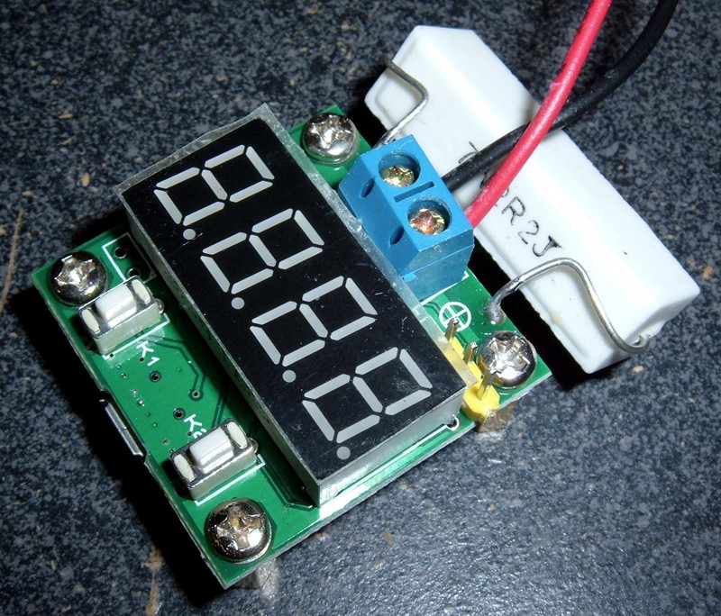

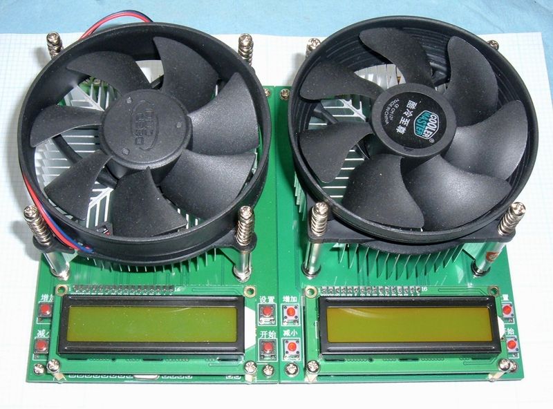
Let’s say you want to measure the capacity of some sort of battery. You’ve found something that looks exactly like this on a website that sells things, and want to know if it’s any good - and also wouldn’t mind a manual written in something that faintly resembles readable English.


Excellent! Hopefully I can be of some use.
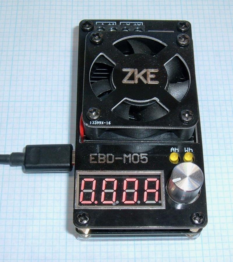
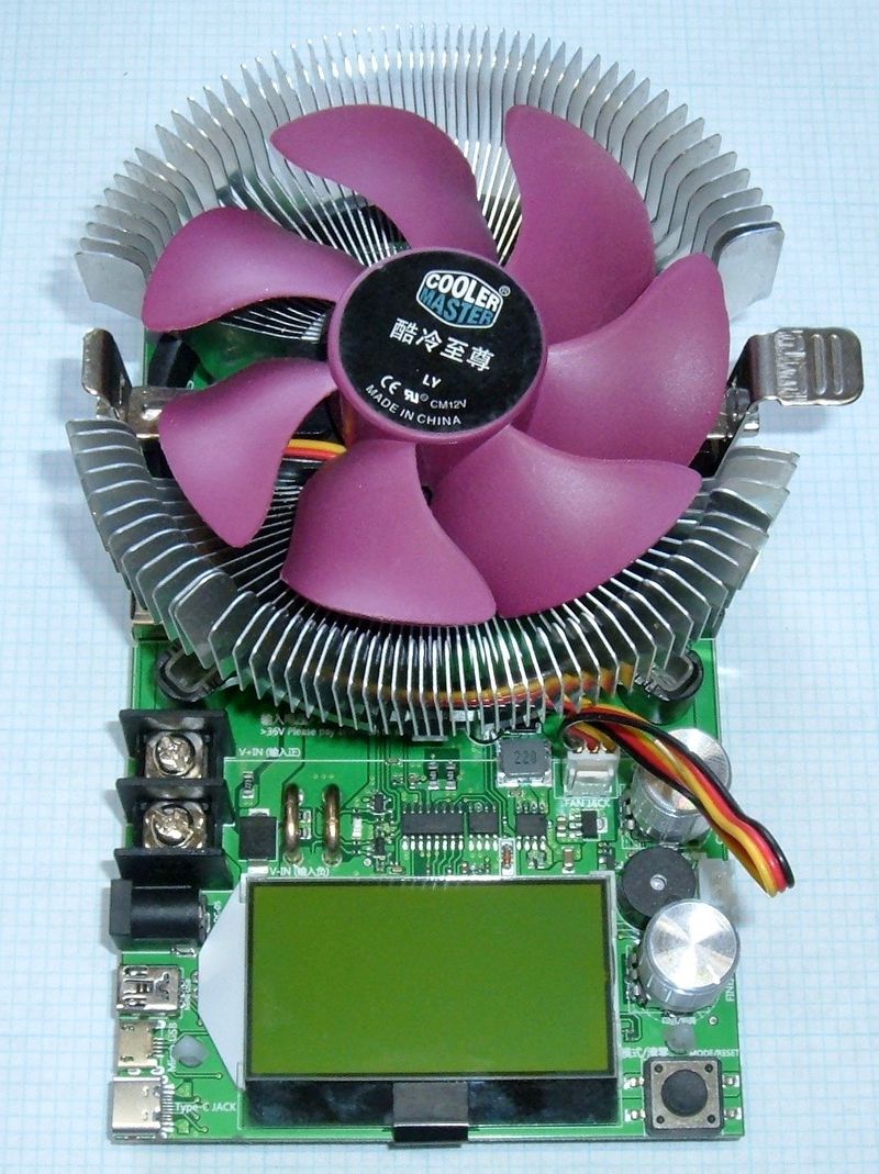
This post is the first of what I intend to be a series of battery testing device testing. I’ve got a bunch of these things showing up, and intend to review and test them, ideally finding the best cheap battery tester for my needs.
This particular tester is a somewhat sophisticated resistor-based battery measurement device. It dumps the battery into a resistor, and measures the current.
Mine came from eBay, and was sold as a Battery Capacity Meter discharge Tester 18650 li-ion lithium +PC online function. I paid $14.52 shipped for it.
The instructions on the website selling it (often eBay) are some quality Google Translate jibberish. I’m going to attempt to translate the important parts, and then try to test it out and see how it works.
If you’re interested, read on. If not, feel free to skip the next post. This is pretty esoteric. However, I did have an excuse to drag out my old oscilloscope, so there’s some great vintage oscilloscope photos in here, if you like such things.
Below my attempts at an actual translation of the provided manual are my operating notes. You may wish to simply skip to these.
Translation Attempt of the Provided Instructions
If you’re buying one of these, you’ve run across the instructions. They’re nearly unreadable. I’ve tried to translate them into something that keeps the spirit of the originals, though there exist parts I literally could not figure out.
Warnings & Notes Before Purchase
- This product (being sold for $11, shipped) is not a professional device. It may be wrong. But, it’s probably fine.
- The battery capacity will vary with temperature, age, and different discharge rates. Using silver plated wire will reduce resistance. Ordinary battery cases have a high resistance.
- This is not a charger.
- If you are measuring 18650s with a protection PCB, the included battery box will not work. Use a test stand.
- Be sure to use a large wire to connect the battery. 22 gauge or larger copper is recommended.
- Brand new batteries are not fully charged - you must charge new batteries before use. A full battery will be 4.2v, and if it shows 3.8v, it is definitely not charged.
- Use a standalone USB power supply to power this device (cell phone charger or such).
- The unit must discharge the battery to test it. It is not an instant test.
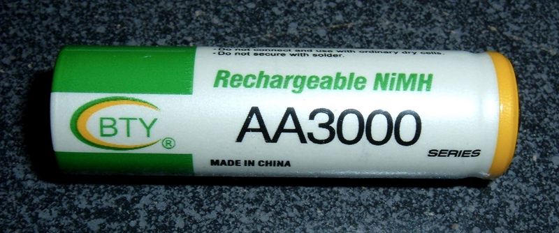
- The tests will take some time. It runs at a maximum of 1A discharge, so a 3000mah battery will take 3 hours to discharge fully.
Features
This product requires a 5v micro USB power source. This product can test lithium batteries, nickel metal hydride batteries, and lithium iron phosphate batteries. It also measures internal resistance. Maximum voltage 5V.
Operating Details
If the battery is 10AH or larger, hold down K1 before plugging in the micro USB power. ”Hcon” will be displayed, and the unit will show up to 65AH capacity. Instead of showing NNN.N mah, it shows N.NNN AH (and probably moves the decimal as things go).
- Insert a fully charged battery in the battery box, or otherwise connect it to the terminals on the device.
- Plug in the micro USB cable.
- The unit will show the battery voltage. For a lithium battery, the closer to 4.2v it is, the more accurate the measurement (assuming your cells are fully charged at 4.2v and not 4.35v).
- Press the K2 key, and it will show the expected discharge voltage. Ensure this is correct.
- Don’t put this near anything that burns! It gets hot! A metal plate is fine.
- The unit will automatically discharge, showing the capacity on the LCD display. When the four numbers are flashing, the discharge is ended, and the number on top shows the battery capacity. (It seems there is some way to mess with the termination voltage yourself, though I haven’t found it)
If the voltage of the battery bounces back significantly after terminating the discharge, the battery is probably no good (it has a high internal resistance).
Don’t overcharge lithium batteries or they’ll blow up (duh).
Press K2 to begin discharge. The unit will show capacity in mah as it measures. Details on the rest of the operation below.
A long press of K1 will show equivalent resistance. Good batteries show around 80 milliohm. The battery compartment resistance will be less than 50 millohm, so you can calculate the actual battery resistance from this.
Termination Voltages
General starting voltage ranges (experimentally determined by me), the indicated symbol, and the termination voltage:
V > 3.6: Ld, 3.0v cutoff (lithium, normal 4.2v charged chemistries)
V > 3.0, V < 3.5, Fd, 2.5v cutoff (lithium iron phosphate)
V < 3.0, V > 1.5: Hd, 1.2v cutoff (nickel-zinc)
V < 1.5: Hd, 1.0v cutoff (nickel metal hydride)
FAQs
- U_L: Low voltage. Check your wiring or your voltage.
- Charge the batteries to 4.2v before starting.
- The lower the termination voltage, the more power is released.
- Alligator clips are not great - the resistance is too high.
- Putting the battery in backwards will not fry the board, as it has diodes.
- The resistor gets hot, but does not need an additional heatsink. Do not short the contacts, or you’ll burn out the tester. The cement is rated to 150 degrees (F? C? probably C) for many days.
- Your maximum input voltage is 5.0v - you cannot test lithium packs.
- You can measure AA & AAA batteries. Somehow. It involves changing programs and I cannot make sense of it.
Syonyk’s Operating Manual
Alright. You want to actually know how to use this thing, in plain English? Here’s the quick guide.
Setup
Battery goes in the battery holder. Or, connect your own preferred battery holder. Note that you should probably tighten the contacts when you get it to make sure they’re fully seated. Use a cell phone charger for steady USB power - apparently many computers emit dirty power that messes up somewhat precise measurements.
Power On Settings
Put a battery in or otherwise connect a battery, and plug the USB power in. The unit will display 0000, then the voltage (briefly), then the battery type detected and cutoff voltage (probably Ld30 for lithium with a 3.0v cutoff), then go back to the voltage display.
If you’re testing something >10AH, hold down K1 while powering the unit on. It will display Hcon and measure in AH instead of mAH. If you hold down K2 while powering it on, it does something else, and I have no idea what.
In this state, K1 (the left button) will toggle discharge amperages. For a lithium cell, your options are 1.00A, 0.50A, 0.33A, 0.25A. Lower voltage batteries offer a some lower amperage settings.

Start Testing
Press K2 (the right button). The display will show the battery type and cutoff voltage (Ld30), the amperage selected, and then go to the main running display. This will count up in mAH or AH, depending on how you powered the device on.
Mid-Test Controls
While the test is running, there are several options.
The mAh or Ah display is the “home” display. Pressing the right (K2) button will show the battery voltage. Long pressing K2 will terminate the test (with the message OFF.1). Note that if you terminate the test, the capacity is saved, so you can change the amperage and resume.
Pressing K1 (the left button) will show you the current cutoff voltage.
Long pressing K1 rotates through the home display, a “load voltage” display, and the calculated internal resistance of the battery/holder combination (rNNN). From either the load voltage or the IR display, pressing K2 will show you a voltage that I cannot yet figure out.
Test Over
When the digits flash, the test is over (the battery has dropped to the cutoff voltage).
Pressing K1 will show you the set cutoff voltage. Long pressing K1 will show you the calculated internal resistance.
Pressing K2 will show you the resting voltage of the cell. Long pressing K2 will reset things.
I hope this is a slightly clearer set of directions than what comes with it…
PC Serial Link
It comes with one. I have the software, but am a little bit hesitant to run random Chinese-provided software on anything I own. I also can’t read the directions or even the folder names, as I don’t read Chinese. If you’re interested in analyzing it, please let me know.
Comments & Analysis
###
Accuracy
Right now, I don’t have any sort of high quality current source equipment - so I’m just going to test a few brand new 18650 batteries and see how it goes compared to other equipment.
During some initial testing with a variable power supply, the voltage shown matches my voltmeter exactly - this is a good start!


Some fiddling around with my power supply indicates that it also does a decent job with the amperages - more or less. And, if I’m honest, I don’t trust my power supply readout very much. So it’s probably fine on the average amperages drawn.
How does it actually work?
This is clearly a more sophisticated device than some. It allows you to set the discharge amperages, and it seems to hold them decently enough. It’s capable of handling a wide range of battery voltages as well, from ~1v up through ~5v - so it can’t be a static resistance involved. And you can’t change the resistance - the load resistor is soldered in place.
The load resistor is obvious. It’s large, cemented, and gets really very hot during testing unless you have good airflow over it. According to the manual, it’s fine to let it get hot, but I don’t like really hot things, so I just stick it in front of one of my window fans when I’m running a higher current through it. 0.25A is usually fine in free air, but unless you want to be very careful about what it’s sitting on, airflow is needed for 1A discharges.
The board doesn’t get hot, so it can’t be regulating power that way. The only logical choice left is for the board to be doing some sort of rapid switching of the battery to the load, and to modify this switching duty cycle based on the voltage and desired amperage.
Fortunately, rapid switching of voltage is just the sort of thing an ancient analog oscilloscope is perfect for! And, if I look in my closet - I’ve got one! It’s an old B&K Precision Model 1470 - dual trace, even! Good to 10Mhz. It’s properly vintage, but it gets the job done. I’m not actually sure how old it is, but I’m confident it’s older than me, by a lot.
So, let’s hook it up and take a look to see if what I think is happening is actually happening.
First, I’m going to monitor the voltage on the load. I suspect, very strongly, that the load is switched on/off aggressively with something close to a square wave. It’s the only thing that makes sense for doing this.
To do this, I hook up my ground reference to one side of the load, and my probe to the other side. I’m guessing that the voltages will match the input sides, since it doesn’t make sense to have positive and negative crossing on the board (not that it matters).

0.25A, 18650@4v
Fire up the tester at 0.25A with a fresh 18650 in it, and… heyo! That looks like a square wave to me! A little bit of overshoot, but what do you expect for $10?

Current settings: the sweep time is set to 2ms/cm (each square is 1cm), and the voltage is effectively 1v/cm (10:1 on the probe, 0.1v/cm… it works out).
I’ve adjusted the vertical offset slightly to make everything fit on the display. Vertically, the ~4v on the load is almost exactly the battery voltage, so that’s good - the switching is just turning the battery-to-load connection on and off. Horizontally, the cycle time is 10ms - 5 squares at 2ms/square. That means the unit is cycling at just about 100hz. I doubt there’s any significance to this beyond “It’s a convenient number.”. It’s running around a 15-18% duty cycle to get 0.25A out of this battery.
Just for fun, I zoomed out to 5ms per cm, and this is what I get: Yes, it’s clearly cycling at 100hz. And I swear I had it adjusted to line up with the grids properly. Parallex error with photography. Still cooler than a bland PNG from a logging oscilloscope.

I’m also really interested in what this is doing to the battery voltage. So, to check this out, I move the scope leads over to the battery terminals on the box (closer to the battery, better reading than the board size of the leads). Alligator ground clip on the left, test lead on the right.

It looks something like this (same settings as above):

You can clearly see the switching going on with the battery voltage as well. It drops, as expected, when the load is switched on.
What’s interesting, though, is that it’s loading the battery up with the full current based on the resistor, for relatively long periods of time. I’m going to come back to this later - but it probably matters, a lot.
The “load” voltage displayed by the tester during discharge seems to accurately represent the loaded voltage, with the non-load voltage being the voltage when it’s not loaded - so as near as I can tell, these two readouts are accurate.
1A, 18650@4v
On the other end of the amperage range for lithium batteries is the 1A setting. Taking the same measurements as above, I get the following displays (and a beautiful, beautiful oscilloscope - this is how you do a science properly).
The load voltage looks as one might expect, at about a 60% duty cycle.

And the battery voltage does about the same thing as above. Look, ma! I learned to use the vertical offset knob! Also, notice that the voltage offset looks the same as in the 0.25A graph. Since it’s just switching on and off, that’s to be expected.

The problem with pulsed testing
So: Here’s the problem with how this charger does it’s testing. It’s always draining the battery at the maximum supported current by dumping it through the resistor, and it’s toggling this connection on and off to achieve the target average current. But, as near as I can tell from my fairly extensive reading on batteries, this just doesn’t matter. Pulsing a battery with high power draw is still pulling a lot of amps out, and you derate capacity based on the peak pulse amperage - not the average. So, if you select a lower amperage, it’s still draining the battery at the maximum rate, just giving it a break between these pulses (100 pulses a second). But you’re still pulsing the battery.
With 1A being a 60% duty cycle, the current draw under load is around 1.6-1.7A. Always. No matter which current setting you select.
If you look at the discharge curves below (for a suitably random lithium cell), notice that at higher draws (higher C rates), the voltage is lower (which I don’t care about for capacity testing), but the final capacity is different as well. You get less capacity (fewer amp-hours) out of a battery when testing with a higher current, and varying the pulse width of the high current pulses shouldn’t change this much.

How big of a difference does this make in practice with modern lithium cells?
I’m not sure. That’s why I decided to test it!
Fortunately, I’ve got a few spare LiCo 18650s laying around - brand new, never used.
These are 3200mah cells (nominal), though I’m not fully charging them (they top off at 4.35v instead of a more normal 4.2v, and I don’t feel like pushing them - also, my charger won’t push them past 4.2v).
A draw of 1.0A is a 0.3C rate, with 0.25A being a 0.08C rate. I don’t have anything that can push them closer to 1C (yet).
My radically involved test procedure: drain them at 1.0A and 0.25A settings, and compare the capacities. They’re all starting with just under 4.2v, and the low voltage cutoff is set to 3.0v.
I then recharge them with my XTAR VC4 charger, and record the recharge current. I’m not expecting them to match perfectly, because there’s inefficiencies in charging, but they should be in the same ballpark, and give me a nice sanity check on the results.
Test Results
Battery A, 1A: 2649mah (drain), 2634mah (charge)
Battery A, 0.25A: 2694mah (drain), 2665mah (charge)
Difference: 1.67% (drain), 1.1% (charge)
Battery B, 1A: 2666mah (Drain), 2661mah (charge)
Battery B, 0.25A: 2671mah (drain), 2698mah (charge)
Difference: 0.2% (drain), 1.4% (charge)
The capacities are pretty close. However, I don’t have a good way to compare these to better discharge testers - yet. Once I have other devices that get me better data, I’ll revisit these numbers and provide better data on how much this matters. There definitely is a little bit more capacity extracted at the 0.25A drain, but less than I was expecting.
Internal Resistance/IR Testing
One really slick thing about this tester is that it can test internal resistance/IR of the battery. Internal resistance is related to the voltage drop measured as the battery gets loaded up. An “ideal” battery would never drop voltage as current increases, but in reality, they do. The IR is the resistance that, paired with an ideal voltage source, would create the observed behavior.
By using the difference between the loaded and unloaded voltage (which it’s pulsing rapidly between), it can (attempt) to calculate the internal resistance of the cell. However, since it’s only a two wire system, what it’s actually calculating is the internal resistance of the cell plus holder plus wiring plus contacts. If this is low, or known, it can get a decent number for the battery’s voltage drop during testing. A better system would be a four wire system (separate sense lines for voltage at the battery terminals), but if your wires are short and low resistance, this system isn’t terrible. Just test with the same wiring each time.
Pros & Cons
Pros
This is a sophisticated tester with (in theory) PC connectivity, internal resistance testing, and a wide range of supported batteries. It’s also very compact.
Cons
The pulsing of the battery doesn’t lead to great test results. And, the load is soldered to the device, so you can’t change it out easily. Having to manually switch modes for a high capacity battery seems a bit silly as well.
Conclusions
This tester does what it advertises, but it does so in a somewhat non-intuitive way. Pulsing the output like this just isn’t a good way to test a battery, and claiming you do a low amperage test when you just pulse a high amperage draw isn’t really very honest.
It does calculate internal resistance of the battery, but if you care about that, you really should be using a 4-wire setup.
Could you fix some of the flaws with this unit? Yes. A large capacitor on the input side would go a long way to smoothing the current, and I might get around to testing this at some point. But, really, in 2015, this shouldn’t be needed. There are better quality battery testers that don’t need this sort of hacking to work.
You probably shouldn’t buy this unit unless you really, really need cheap PC logging, don’t care about a pulsed discharge, and can deal with the software being Chinese.
Comments
Comments are handled on my Discourse forum - you'll need to create an account there to post comments.If you've found this post useful, insightful, or informative, why not support me on Ko-fi? And if you'd like to be notified of new posts (I post every two weeks), you can follow my blog via email! Of course, if you like RSS, I support that too.


