
At this point, having read the title, you can probably guess my overall opinion on this little work of art…
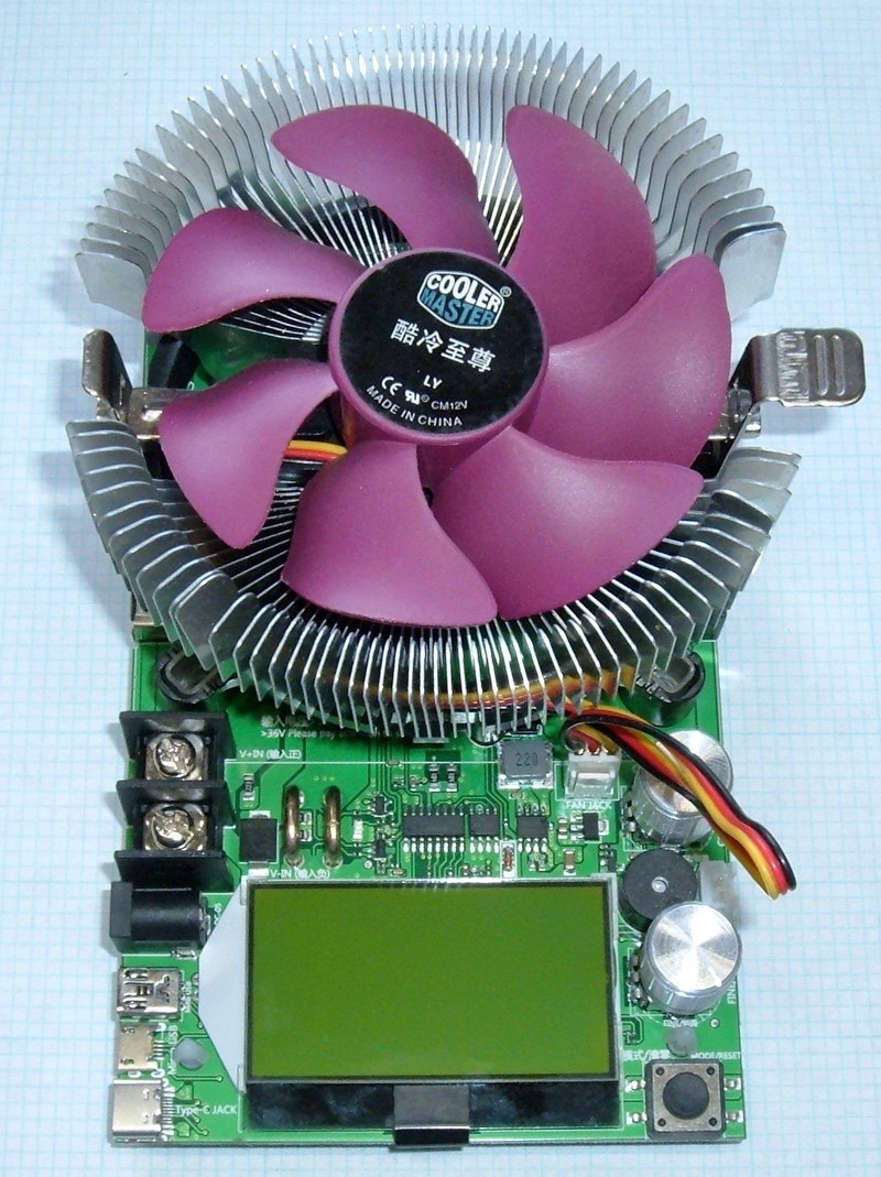
Following up my previous review of some 150W load banks, I’ve got another load bank on my bench for analysis. This one is alternately sold as a 150W discharge tester, a 185W discharge tester, and probably other stuff I haven’t found. It has a purple fan, a high resolution LCD, and two knobs on the right, plus a boatload of USB ports for input.

And it’s a steaming turd of a unit you should never purchase. However, I did manage to get most of a review in (and a lot of MOSFET replacement practice). It does work, for limited values of work, so come see what I found!
The ATORCH Discharge Tester/MOSFET Destroyer
As is usual here, I’m going to detail the unit features, pull it apart a bit, and then cover operation, accuracy, and, for this unit, failure modes and why you shouldn’t buy it.

On paper, this is a pretty exciting little unit. It’s rated for 200V, 20A, 150W (or more, depending on who is advertising it), and it comes with a wide variety of input connections. From left to right, you’ve got a USB A connector, a pair of solid screw terminals, a barrel plug, a mini USB connector, a micro USB connector, and a USB-C connector. I don’t think the USB-C connector does power delivery negotiation for higher voltages (at least, I see no evidence of this, and don’t care to blow up a USB charger to find out).

Flipping the board around, we’ve got the controls and output side. There’s a button in the lower left here that handles (via arcane button presses) the control of the digital side. The “fine” and “coarse” knobs control the current through the system, there’s a little beeper, a two pin jack whose function I have not discerned (I’d expect it’s current control via analog voltages, but am truly tired of replacing MOSFETs), and, interestingly, an output barrel plug (on the right). This is live to the input, and seems useful for chaining devices together if you want more power capacity. Unfortunately, this sort of barrel plug isn’t good for more than a few amps (reliably), so I’m not sure what actual benefit you’d get from chaining devices. A pair of screw terminals would be radically more useful as an output.

On the back of the unit, there’s another fan jack (unused), and a few options for powering the unit. Both are labeled “6V ~ 12V” - which is a really weird thing to do with micro-USB, which is almost always 5V. And if it’s not, it’s because something negotiated higher with a supporting charger. Despite requiring (supposedly) a minimum of 6V, the unit appears to work just fine on 5V from micro USB.

But, just to be safe (while testing), I’m powering this from 12V. I have a bunch of these little boost converters ($2 on eBay) that have a micro USB port on them, and I love them for this sort of work. I’m using one to power my DSO138 oscilloscope, I use them for these devices… they work perfectly for anything that doesn’t draw much power and needs an input voltage around 12V. Having everything in my office be USB powered is sort of awesome, and it also means that I can easily use my equipment on the go with a USB battery pack.

Diving Inside
The heatsink comes off by driving the “wedge pins” out, and then pinching the spread wedge on the underside to let it pass through the PCB. It’s a far inferior setup to the screw type heatsink on the other units I’ve tested recently. With the heatsink off, you can see the full top of the board (there’s nothing interesting on the underside). In the center, there’s a big power MOSFET that handles the load. For an electronic load like this, the MOSFET operates in between fully off and fully on - which, functionally, makes it an electrically variable resistor. Change the gate voltage, you change the resistance, and that changes the current. All that energy is then dissipated as heat inside the MOSFET, explaining the huge heatsink on top.
In the center, above the LCD, there’s the digital control section, as well as a pair of shunt resistors (the fat wires to the right of the screw terminals). Yes, wires are resistors, and if you forget this, you’ll have trouble with circuit board design. To quote someone I greatly respect, “The number one problem with entry level board designers is that they reliably forget that copper is not a superconductor.”

I really like the touch of all the big vias in the power section. Some of the advertisements for the board talk about increasing the power handling capacity by adding a big heatsink to the rear, and from a thermal perspective, that would work fine_._ Adding more heatsinks, to handle more power, probably won’t fix the board blowing up the MOSFET, though.
The stock power MOSFET is an IRFP264. This is a 250V rated power MOSFET (voltage controlled transistor), rated for 24A at 100C. It should be fine - though, you’ll note, I’ve already replaced the stock part…
Next to it, on the left, are a pair of 43CTQ100S rectifiers - diodes. They’re 100V parts, so I assume they’re in series to meet the 200V requirement, though this doesn’t really work as well as one might hope without some other components that seem to be lacking. I wouldn’t take this board anywhere near 200V.

Digging further into the digital section, we’ve got a diode on the far left, the shunt resistor (the fat wires) to measure current, various control circuitry, and the fan jack on the far right. What are the various ICs on the board?

The left part, 00R6J0A, is one I cannot find any reference for.
Next, the MK 24C32B 1706 - also, mystery part.
Finally, the MC34063A? That’s a DC-DC converter.
That said, I did find one reference for the 24C32B - it’s the same part used on a lower power USB load bank! That unit is rated for 25V, 4A, and 35W. We’ll come back to that later, but, suffice it to say, the controllers on this board are quite the unknown. One of these is going to be the display controller, and the other is the microcontroller. I’d guess the bigger one is the main microcontroller.

Operating Notes
Power the unit on, connect your battery/power source/etc, and you’re ready to play!
The two knobs on the right control the current. The top, “Course” knob, adjusts the current in large steps. The lower, “Fine” knob, gives about 2A worth of adjustment range. These are analog knobs - no exact current setting here. You can get close, and it may drift over time (though I never had mine running long enough between blowing up MOSFETs to observe this). You’ll want to turn these all the way counterclockwise before hooking up a load (that sets zero current). I’m not sure what the maximum current actually is - the unit claims 20A, but I’m not about to hook up something capable of sourcing 20A to this unit, because my 20A sources don’t exactly have limits on them.
There are lots of status screens, and you toggle through them with the button on the lower right. Plus do everything else with that button. One button interfaces suck, as you will soon learn…
I don’t know why it shows “OFF” in the lower right - it’s clearly on, as shown by the 0.97A in the upper right.
In all of these screens, holding down the single button until the unit beeps will reset time, amp-hours, watt-hours, etc. You can reset individual values (and the stock instruction sheet below demonstrates this), but I can’t imagine why you’d want to.

Cycle forward, you get the same display, but with English labels. Stuff is pretty obvious based on the units - the top entry is the current voltage, capacity is in amp-hours, energy is in watt-hours, time is the thing that counts up, current amperage is in the top right, I have no idea what the (1.00) field is for, and the unit temperature is in degrees Celsius.

Would you like the same data in bigger values? You can have it!

Would you like big numbers on the left? You can have that, too! Interestingly, this mode adds Ω reading in the lower right. I don’t know if it’s accurate or not - this unit is attached to my lab power supply, not a battery, because it’s blown up the MOSFET multiple times already, and I try to avoid shorting battery packs out in my office.

Moving on, the next screen is “BL:ON” - this refers to the backlight.
Now we get into the weird single button interface of this board. You double tap the button to increment a value, and triple tap it to decrement the value. Then, if you press and hold, the value will continue moving the last direction you moved it. The trick here is that the time for a double tap or triple tap is really short. For the triple tap, you need three taps in well under half a second. If you’re slow, it’s impossible to move the value down. Since important values are set here, you’ll need to figure this out. It’s one of the worst interfaces I’ve ever run across, and that says something.
Anyway, the backlight control. “On” is the permanent on setting, which you probably want to leave. But, because I explore weird features, you can drop it down to 59S or lower, at which point it will turn off after the set time. If you drop it down to 0S, it shows “OFF” and is never on. Why would you use this? I have absolutely no idea. Just leave the backlight on.

Moving on, we have an overvoltage warning. Set, by default, to 300V. On a unit that has a 250V rated MOSFET, 200V (optimally) of diodes, and that I reliably blow up around 40V. The same approach to setting it applies as above, and you can set it wherever you want. I have no idea what happens when you exceed this, but I can say, with confidence, that I wouldn’t put 300V anywhere near this unit. Except to blow the whole thing to pieces, which I’m considering doing.

Next, there’s a low voltage alarm value. This, sadly, doesn’t do what you’d hope. It will beep and disconnect things when the voltage drops below this set point, but if the voltage bounces back above (as might happen if you’re hammering a battery bank pretty hard), it’ll kick the current back on again, and toggle things until the open circuit voltage is below this point. It’s sort of the worst of all possible worlds in terms of cutoff behavior, except for what this unit also does, which is to blow out the MOSFET, short the load, and never cut off. However, if that happens, something is likely to fuse open.

You can also set the overcurrent alarm. Again, I’m not entirely sure what this does, but since the digital side seems to have very little to do with the analog side, I expect it doesn’t do much but beep at you. Do you really want to trust this little unit with 100A? I thought not…

Finally, you can set the maximum permitted power. Like the other high limit settings, I haven’t been able to play with this without blowing the MOSFET, so… it’s here, you’re on your own if you get close to it, and I wouldn’t get anywhere near it.

Basically, hold the button to zero the values, turn the dials until you hit the desired current, and then, depending on how your source behaves, it’ll either cut off at the termination voltage, or sputter along. It’s not terribly useful unless you want to gently run up the current to find out where a power supply limits, or something like that.
If you want the stock instructions that are often provided with it, adding a bit more detail on how you could, say, clear amp-hours without clearing watt-hours (why you’d want to do this is beyond me), here you go! Click on it to see a full size version.

Accuracy
The datasheet claims an accuracy for voltage of “0.05V” and the same for current - 0.05A. I don’t know if they mean +/-, or absolute error, but it doesn’t matter that much. Below 10V, the display shows two decimal places on voltage, and above 10V, only one. I did some random voltage testing, and I’d say it’s generally within 0.05V. Nothing particular precise, but it does generally sit within the specified tolerances.
Amazingly, for current, it also sits within an absolute 0.05A error. The unit reads consistently low compared to my BK Precision meter, but it’s within 0.05A. So, despite not being particularly tight, it does meet the claims made for accuracy.
The Nature of the MOSFET Destruction
This thing is an exceptionally effective MOSFET destroyer. I’ve replaced three fried MOSFETs during this review, and that’s a new record. One failed open, two failed shorted. A shorted MOSFET is annoying if you have a current limited source like a USB power bank, and it’s downright dangerous if you have something else like a battery pack attached. I can’t find a fuse on the board. Something will fuse. I’m just not sure what. I may try this at some point, in a safe area. I’ll get video, don’t worry!
But, in any case, I’m curious. And when I’m curious, I tend to do things like pull out my scope, stick it on the gate-source pins, and see what’s going on. If you’re going to destroy a MOSFET, it’s almost certainly going to be by violating the gate-source voltage limits. Looking at the data sheet, the absolute maximum gate-source voltage is 20V. That’s not “Oh, run it at 20V and you’re fine” - that’s “Do not exceed +/-20V between gate and source at any point in time or you are damaging the device.”

What’s this unit put across the gate-source pins? I set my lab supply to 40V/5A, and did some testing. The highest I caught before I gave up was 27.6V. Yeah, that’s 38% over the absolute maximum. Let’s take a look at the spike! For whatever reasons, the when running the MOSFET “wide open,” there are regular voltage spikes in the form of a bit of very high frequency ringing. The amplitude of the ringing is around 37V, with the peak positive voltage being the 27.6V previously noted. On a part with an absolute maximum rating of 20V. So, that’s why it dies!

And it does this a ton. These ringing spikes are very, very frequent when it’s operating wide open. On this trace, the time unit is set to 5ms - so each line, horizontally, is 5ms. You can see it’s getting that ringing very regularly, with some of them quite high. I don’t have exact values for the frequency, but it’s a problem - and, empirically, it kills the MOSFET in a hurry. Bad designer.

What do I mean by “wide open”? I have this device attached to a bench power supply that limits the current around 5A. I used to test my load banks on a battery pack, but some previous experiences with load banks blowing up led me to prefer something a bit tamer that can’t put 100+A through a failed MOSFET. I don’t like DC arc faults, and I don’t like PCBs exploding, overheating, or catching fire in my office. Yes, every board has a fuse, but not every board has a designed fuse.
In any case, the plot below is what the gate-source voltage looks like as I sweep the current knob up and down. On the left, the voltage is zero - MOSFET closed. No current flowing. As I start turning the current set knob, the voltage across the gate rises suddenly to about 3.5-4V. Per the datasheet, this is where the part turns on initially. No problem. The voltage rises smoothly as I request more current, and there are some spikes, but they’re not nearly as high as I see later.
Then, there’s another sudden spike in the control voltage. This is when my power supply starts limiting the current. The load tester wants 6A, but only sees 5A - so it tries to open the MOSFET wider and wider until it’s wide open. That’s around 7.8V on the gate, which would be fine - except for those spikes. You can see how the top line looks hairy - that’s voltage spikes all over the place, and those are what are pushing the gate-source voltage over 20V.
Then, as I turn the current control knob back down, you can see when the requested current drops below what my lab supply is limiting at, and it goes back into the range of operation around 4-5V that sets the desired current.
My initial thought was that somehow the supply voltage was leaking through to the gate control voltage, but when my supply goes into current limiting mode, the voltage across the terminals goes to nearly zero (the supply reports about 1.8V, but there are a few connections in there, and I’m not sure what, exactly, is going into the MOSFET - in any case, nowhere near 40V, and far closer to 1V).

The ringing behavior when operating within the bounds of what the power source can provide isn’t as bad, but it’s still present. Given the new kid around, I didn’t have the time to fully plumb the depths of the behaviors, but it doesn’t matter. A load tester should not, in any conditions, be blowing up the MOSFET by violating the absolute maximum supply voltage.
If you’re designing electronics that use a MOSFET, how might you fix this? Well, first, if you’re doing analog design, you need a high frequency scope to observe this behavior. For all I know, the people who built it don’t even know it does this. But, beyond that, you should, at a minimum, have a zener diode to clamp voltage spikes going into the MOSFET. I’d probably put a 15V pair on here, but there should be something in the way.
Searching for “mosfet gate ringing” gives an awful lot of results. This should be something you pay attention to in the design stage of a device, and clearly someone didn’t. It’s not a problem if it doesn’t blow up MOSFETs, but this does.
One might consider putting a more robust MOSFET in place, or hacking in some clamp diodes, but… why? This isn’t a very good load bank to begin with.
Final Thoughts & Conclusions
Normally, I’ll finish a review by talking about what the unit is good for, what it’s bad for, and what you might consider buying it for.
This unit? Do Not Buy. This one, or any that look like it (I’ve seen some with different heatsinks). There’s just no reason to buy this unit, with it’s many faults. Even if it didn’t blow up the MOSFET, I’d not be a fan - the analog control is imprecise and the digital system is poorly implemented. Not being able to set a cutoff voltage and have it terminate (and stay terminated) makes this nearly useless for battery testing. And then it blows the MOSFET regularly, which is downright dangerous. Maybe, if you were testing raw battery banks, it wouldn’t blow as often because it wouldn’t be wide open, but do you really want to risk it?
And then there’s the “200V” rating based on diodes in series. Not OK. Things don’t normally work like that, and I see no evidence that this board is designed to work around that. Diodes just don’t share voltage equally as they age.
It might be an evolution (or copy) of the USB tester I mentioned earlier. I’m not sure, but there are a lot of similarities, including the same unlabeled microcontroller, that I’d be willing to wager that the two are related somehow. If you know, I’d love to find out in the comments.
If you were using this to test USB power supplies, and didn’t mind replacing MOSFETs regularly, well, it would probably work. That’s the only use case I can think of where the behavior is acceptable, if genuinely annoying. Although, it’s not hard to build some adapter cables from various USB connections to a couple wires…
But, seriously. Don’t buy this unit. It’s junk. Try to find one of the legitimate units I reviewed two weeks ago.
If you want to reverse engineer, improve, or otherwise have a cheap little unreliable tester to mess with, just ask. I’ll send this pile of rubbish your way for the cost of shipping.
And, if you are curious about if a particular cheap load tester is any good, feel free to ask. The contact form is over there in the right column, and if you wanted to send one my way, I’d love to beat it up and see if it’s any good. If you build these units, and want an independent analysis, send me your best and I’ll see what I can do!
Finally, if you find these hardware reviews useful, there’s a little donate button over there. I solemnly swear to put all donations to no good use whatsoever, buying cheap Chinese gizmos to rip apart, blow up, and otherwise poke and prod until I understand them!
Comments
Comments are handled on my Discourse forum - you'll need to create an account there to post comments.If you've found this post useful, insightful, or informative, why not support me on Ko-fi? And if you'd like to be notified of new posts (I post every two weeks), you can follow my blog via email! Of course, if you like RSS, I support that too.


