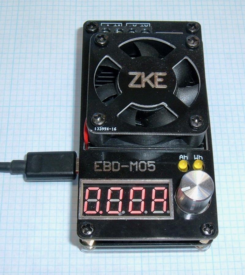

I haven’t reviewed a battery tester in a while! This week, I’m covering the Very Fancy ZKE EBD-M05. This is a 19.5V, 5A, 30W battery tester with a rather slick computer interface, and some properly impressive accuracy (once calibrated). Plus, it measures watt-hours!
I’ve subjected it to my usual battery of tests, and it’s good. Very good! It’s well worth the $20 on eBay - and if you want a battery tester at this point in time, you should probably buy this one!

It solves most of my complaints about other units I’ve used, and with software that actually works, it’s my new favorite battery tester!
Read on for all the details!
The EBD-M05
This is yet another battery tester. I’ve tested a few of them in the past.
A battery tester is typically a pretty simple device - it’s a way of discharging a battery through a controlled load of some variety, so you can measure the capacity of the battery (in amp-hours, but good ones also give you watt-hours). They also normally give you control over the cut-off voltage - when it stops the test. This allows you to not destroy a battery in the process of testing, because many battery types don’t like being deeply discharged (lead acid and lithium are both damaged severely by being fully drained to 0V). A configurable cut-off voltage also lets you test the battery for your needs and system voltages. I might find a lithium cell that’s rated for 4.35V, and the capacity number is from there down to 2.5V, which is right on the edge of battery abuse. How much capacity does it have if I charge it to 4.2V (easier on the cell) and drain it to 3.0V (also easier on the cell)? I’d have to test one to find out.
This tester is actually quite flexible. It’s rated for up to 19.5V on the input side (which lets you test packs instead of just bare cells), up to 5A on discharge, but it will self-limit to 30W. This means if you’re testing a 15V battery bank, you can only pull 2A, but you can test a 3.7V lithium cell at 5A without any trouble. Full rated voltage (19.5V) at 5A is nearly 100W, and the unit simply won’t dissipate that, so they limit it. It works, and it keeps the unit alive, which is far better than I can say of some other load banks I’ve messed with over the years.
The unit has a very simple interface on the front - a knob (that you can push), a 4 digit 7 segment display, and two LEDs (to indicate amp-hours and watt-hours). The knob is sturdy, and it’s a rotary encoder knob, not an analog control (so it clicks into a number of positions and lets you set values accurately).

The back contains the connections to the battery under test. It’s a 4-wire connection, which is awesome. A 4-wire connection uses separate voltage sense leads to accurately measure the voltage at the battery terminals, instead of using the current carrying wires (which will have a non-trivial voltage drop over them at higher test currents).
Unlike some other units I’ve tested, that feel the need to use a 4-wire connection as “two separate connections to parallel together most of the time,” this unit behaves properly - the voltage terminals only measure voltage, the current terminals only carry current. This is how a good 4-wire system should behave. The 4-wire system is mostly useful when measuring watt-hours, but it also helps with accurate cutoff voltages.
Connect your battery bank and go. The V+/V- connections are not optional - everything needs to be hooked up.

Power for the unit (and serial communication, if you care to use it with a computer) are provided by a micro USB terminal on the side. You can see the heatsink and fan stack here - it’s a bit less than I might use for a similar system, but it seems to work fine in practice. There’s also a little rubber bumper on top of the micro-USB port that helps prevent stressing the port - it’s a nice touch.

Ripping it Apart
The M05 has a nice looking clear back plate on it, and a protective cover plate over the top. For a $20 unit, this is really, really nice - I’m not used to seeing anything but bare PCB in this price range (or, for that matter, far higher price ranges). However, it being in my office, the cold screwdrivers are coming out.

After removing the screws from the top, the whole thing comes apart into the three layers. The top board (on the right) is nothing but decoration - all it does is make the unit look better. I’m really quite surprised it’s included at this price range, but I’m not one to complain. I wouldn’t care if it was bare, as long as it’s good.
Interestingly, the core board is labeled EBD-MINI - which is apparently several products, based on the sale pages I’ve found (some of which look like this, some of which don’t).

The top of the core board doesn’t contain much interesting - controls, the display, terminals, and a heatsink/fan. All the good bits are on the bottom, and you can see some of them below!
The load transistor is an IRLZ44N - a 40+A, 50W rated unit. Running at 5A and 30W, this should last nearly forever - and I haven’t blown it up in testing so far, which is better than I can say about some the rubbish I’ve tested. “Doesn’t blow up during testing” is, sadly, an achievement some hardware can only dream about. I don’t deliberately abuse equipment, but if it says it can handle 60V, I’m going to run it up to 60V while testing it.
Just to the right of the silver 16MHz oscillator in the center of the board, there’s a STM8L151 - a little microcontroller with a 12-bit analog-digital converter that’s just perfect for something like this. The modern world has no shortage of good microcontrollers, though it seems we’re a bit short on people who can write good firmware for them.
Towards the top, by the USB port, a Prolific PL2303SA USB to serial adapter chip covers communication to the microcontroller. It’s not an FTDI, but it works out of the box in Windows 10, so I can’t complain too much.
JP4, in the center of the chip, is almost certainly a programming interface of some sort. I haven’t scraped up the desire to reverse engineer this board, but if someone else wanted to, I’d certainly be interested in the results!
The lower chip is a MCP6001 op amp, and the chip in the top left is a LM358A dual op amp. These are common in load testers for voltage buffering - allowing something to read the voltage across a shunt resistor without disturbing the measurement.

Using the EBD-M05
Use is pretty simple. Plug it in, connect the battery. Hold down the rotary knob, and you can set (by digit) the current (A), and the cutoff voltage (V) over the valid ranges, by 0.01A/0.01V increments, if you wish. The digits roll over properly, so 0.90V will roll to 1.00V if you’re messing with the center digit.
As near as I can tell, cutoff voltage is the under load voltage - not the unloaded voltage. Some battery testers use under load voltage, some use unloaded voltage (disconnect the load, measure voltage, reconnect load), some let you select. There’s nothing wrong with either way, but you should be aware of what you’re dealing with, because the two results aren’t identical under heavy load. I personally prefer under load voltages, as a BMS will cut load based on the actual, under-load voltage. A lithium cell that sags to 2.5V under load but springs back to 3.5V after the load is released isn’t a good cell for whatever load is being applied.
Hold the knob down again to exit the setting mode, then press it to start the test. The fan will crank up, and you’ll be able to scroll through the values (volts, amps, amp-hours, watt-hours) with the knob. When the cutoff voltage hits, the test stops, and you can see the final values.
Really, really simple - play with it a bit, and you’ll get it. There’s only so much you can do with a single knob, but it’s enough.
However, this unit’s strength really isn’t in the standalone use - it’s that it has useful software!
The EBD Software
The strength of the EBD units is that they come with software - and, not just software. Usable software! In English! Seriously, I’m excited.
You can find the software many places, but I’ve mirrored a copy: https://github.com/Syonyk/EBD-M05 Just in case other sources go away. It’s quite straightforward, and if you want, it even has a pretty solid manual (also in my repo). This is a readable enough manual that if you’re playing with the software, you should go read it yourself.

While running, you get nice voltage/current curves, current raw data, calculated data… it’s pretty sweet. Here, you can see the unit maintaining a 30W output load. I ramped up the voltage (shown in the blue line) while testing with a high current, and you can see the current (red line) dropping down as the unit throttles the current to stay below the design power of 30W. Very nicely done.

The software offers a few additional features, like internal resistance checks (at specified currents), logging, automatic testing (useful for finding out when a power bank or USB power supply quits), etc. It’s surprisingly flexible, and I’m quite happy with it.
Accuracy: Factory Calibration
Armed with my bench multimeter, a power supply, the M05, and the desktop software (it shows higher precision than the unit), I set out to figure out the accuracy out of the box.

The unit is rated as a +/- 0.5% accuracy unit, and possibly +/- 0.005V (depending on how you read things). I ran through a voltage sweep, comparing the unit output to my multimeter output, and other than some percent error at the very bottom end (if you’re off by 0.001V at 0.10V, that’s still 10% error), it’s dead on. Above about 1.5V, it’s easily within 0.5%, and for most of the voltage range, it’s within about 0.2% of my meter.

The unit can be calibrated, but it’s within the tolerances of my meter (which is, as of this post, in for calibration - it’s capable of 0.02% accuracy, but hasn’t been calibrated recently), so I’m going to leave it alone for now, and say that other than a bit of offset down low, it’s amazingly good.
Current, out of the box, is another story. The low current offsets show up again, but it’s still really, really bad out of the box. It settles in at -5%, which is far, far outside the 0.5% spec it should be capable of.

Time for Calibration!
Fortunately, this unit supports calibration (through the desktop software)!
You can calibrate voltage or current through the same interface. If the unit isn’t passing current, you can calibrate voltage, and if it is, you calibrate current.
Set a low and high voltage (for whatever values you care about), and report the actual value from your high precision meter in this dialog box. The manual suggests “below 4.5V” for the low voltage option, and “above 4.5V” for the upper one. Once my meter is back, I’ll play with calibration a bit more, but be aware that it’s an iterative process. Calibrate it, then see where it is, and you have smaller and smaller errors over time. You might try calibrating at different voltages each time as well - I don’t know exactly how the algorithm works.
Current calibration is the same. Let the unit run (so it’s passing current), and report the actual current your meter shows in the dialog box, then iterate a few times.
Calibration is stored in the unit, so it should stick over power cycles.

Accuracy: Post-Calibration
After iterating on the current calibration a few times, I had the unit running hard (4.70A), and saw this on my meter - this is an improvement!

It holds this accuracy across the current range. Post-calibration, it’s slightly out of spec at the bottom end (and I didn’t specifically calibrate at 0.1A), then slips inside the 0.2% range by 0.3A and sits comfortably within for the rest of the range. I’m fairly certain I could get this even tighter if I tried, but it’s easily within spec. If I use the +/- 0.005A range, things are easily within spec - the unit was passing 0.0993A when set to 0.1A, which is still really, really close.

For capacity tests, I tested the unit against a selection of my other capacity testers, and it’s comfortably within what I consider reasonable (a few percent - I have no guarantee my charger is absurdly accurate). At some point, I really should put together a better test for capacity measurement than “measuring some test batteries on different testers,” but it’s right in with the other meters I use.
Other Random Notes
The lowest voltage the unit will report is 0.08V - which is stone dead, for just about every battery.
The reported voltage changes from 3 decimal places to 2 decimal places at 4.5V. Based on the software manual suggesting calibrating above and below this voltage, I’d guess the hardware is shifting ranges here.
Above 10V, the on-unit display shows only one decimal place, but the software shows two. Making me happy, it rounds properly - if the software shows 10.46V, the display on the unit will show 10.5V (I’ve seen others that truncate).
Depending on your calibration, you may end up with somewhat less than 5A maximum current - after I calibrated, the maximum current I could pass was 4.73A - but it was an honest 4.73A, which is what it had been passing originally when reporting 5A out of the box.
Final Thoughts
I started this blog with a few battery testers, and they’ve gotten steadily better over the past few years. This unit, paired with the USB serial interface, is incredibly capable, and once calibrated, the accuracy is as good as anything I could ask for in a $20 unit.
One of the huge things this unit offers compared to other testers is the 19.5V upper voltage limit. You can test up to 4S lithium packs without trouble (useful for those with RC flying things), though the current is limited at that point. You can still get solid amp-hour comparisons on packs over time, though, and the accuracy is great.
My only real complaint is the factory current calibration - it’s just really, really bad. If you have a halfway tolerable multimeter, calibrate the unit first before you use it. I wonder if there’s a market for selling pre-calibrated meters?
This gizmo having a serial protocol, the next obvious question is, “Have I reverse engineered it?” And the answer, sadly, is “Not yet.” I can tell you it’s 9600 8E1, and it’s easy to sniff the commands from Windows, but I haven’t had the time to sit down and reverse the protocol yet. It doesn’t look hard, and I’ll probably do it at some point, but I can’t give any estimates. If you feel like doing it, please, go for it, and let me know when you’re done!
Comments
Comments are handled on my Discourse forum - you'll need to create an account there to post comments.If you've found this post useful, insightful, or informative, why not support me on Ko-fi? And if you'd like to be notified of new posts (I post every two weeks), you can follow my blog via email! Of course, if you like RSS, I support that too.


