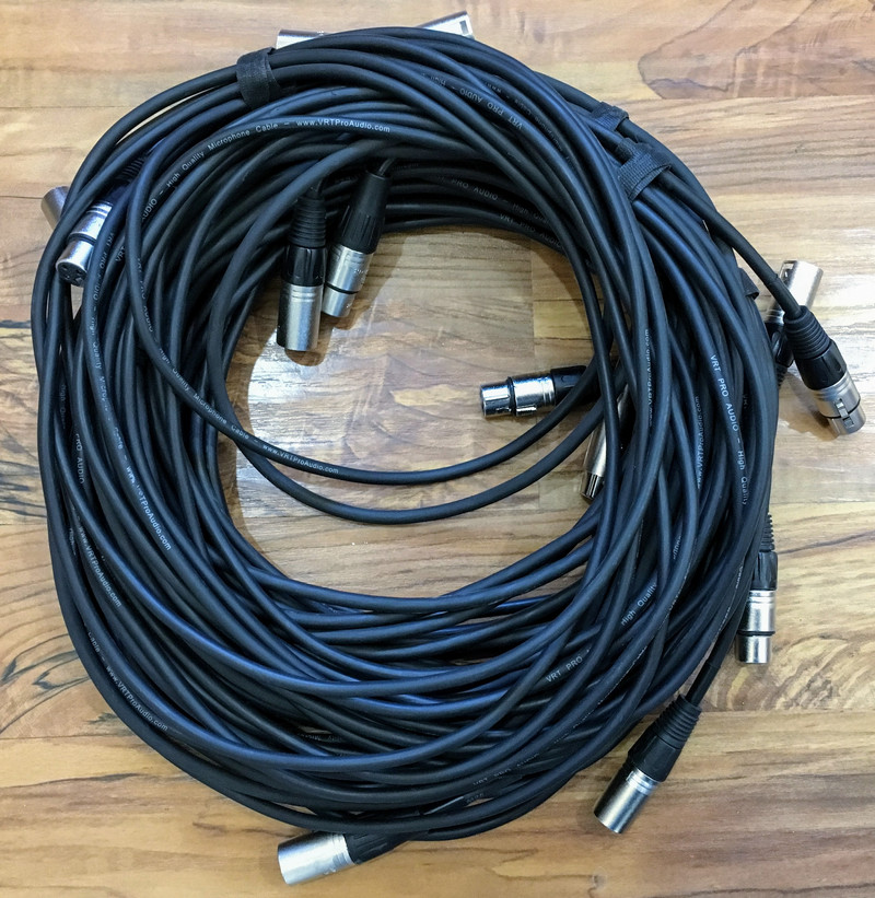

XLR cables. DMX cables. Silence. Darkness. Snaps. Crackles. Pops - and not the yummy Rice Crispies kind. These are the kind you get on a Sunday morning (or Friday night) when something’s gone badly wrong with one of your XLR cables (or DMX cables), and the problem is almost always at one of the ends of the cable.

What’s gone wrong? How can you fix it? What might prevent it from happening again? I’ve spent a chunk of time repairing cables, and I’ve found some methods that, if applied early, should help keep your cables living a long and robust life on stage!
Church Planting, Mobile Churches, and Touring Use
Much of this advice is focused towards those using cables in “touring use” - weekly (or more often) setup and teardown. If you have a permanent facility, that’s great! But, you’re probably not destroying cables terribly often, so this may be a bit less relevant to you. If the cables are fixed in place and not being, say, connected, disconnected, wound, unwound, banged down the road, and subjected to temperature extremes weekly, they’ll probably hold up just fine.
But if you do subject cables to that sort of abuse, there are a few cheap things you can do to help them last far, far longer. Plus, even if they do fail, it’s cheap and easy to fix them with new ends so that they hold up and don’t fail again!
Why do I mention church plants? Because they’re probably operating on a shoestring budget, and aren’t buying the expensive, exotic, “touring” grade cables out of the gate. But it doesn’t matter, because with a hot glue gun and a cheap cable, you can make something almost as good!
XLR vs DMX Cables
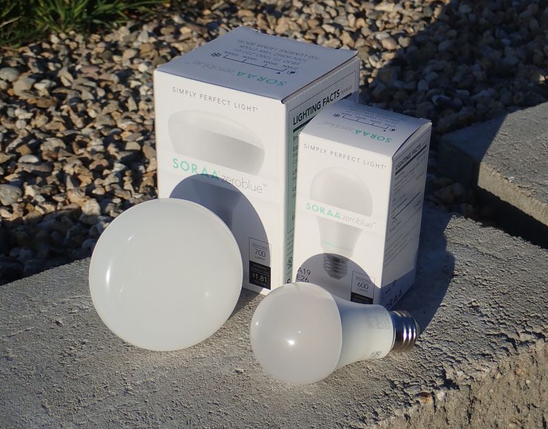
Originally, the DMX spec required 5 pin connectors. It still, theoretically, requires 5 pin connectors, but nobody ships cheap lighting gear with 5 pin connectors. It’s all three pin - which, conveniently, is the same connector that XLR cables use (mic/instrument cables). It’s tempting to think that the cables are the same, and, in reality, they do work the same for short distances. But, if you’re buying new cables, buy DMX cables for everything. The DMX cable spec is more tightly defined than the spec for audio cables (mostly because it’s operating at a far higher frequency - DMX is operating at 250kHz, audio is operating in the sub-20kHz range). This means that a DMX cable is a perfectly good audio cable, but an audio cable may not be a perfectly good DMX cable. Over a short range, it doesn’t matter, but the cost difference is minimal, so you may as well buy DMX cables for everything when you’re setting up a new church plant.
Of course, if you have piles of cash, you can buy really expensive cables, but that’s not how any church plants I’ve know work, so, buy cheap, and then make them better for the investment of a few hours of time and equipment you probably can borrow from someone!
XLR and DMX Signaling
Both standard balanced audio and DMX signaling can be run over a normal three pin cable, as they (typically) use the same pins for shield and signal. Both signals are differential (the audio term is “balanced,” but it means the same thing, just in the analog realm), which means that one conductor carries the positive signal and the other carries an inverted version of that. These two conductors are twisted together, and surrounded by the shield wiring. Here, I’ve pulled the shielding (which normally wraps around the entire core) aside to show the signal conductors and core supports on a fairly nice cable. You can see the red conductor spiraling around on the left, under the sheath. The other white stuff is strands of string, which adds strength to the cable and helps prevent the conductors from being kinked (which can do very bad things to a signal - a bad enough kink will reflect the signal back and cause all sorts of problems).

Why does this matter? If there’s electromagnetic interference (common in stage environments), the twisted pair will help cancel it out (half the loops are facing one way, half are facing the other way). If you do get common mode interference, it impacts both lines the same, which, when you subtract the signals out at the end, means it cancels out. Both balanced audio (analog signals) and DMX (digital signals) use the same arrangement, and there’s no need to dive into the EE details. But, you have two conductors, a shield around them, and all of them matter.
XLR Cable Failures
If you just buy cheap cables and run them as-is, they’ll work for quite a while. Experimentally, you’ll get at least a year from cheap cables in weekly use, and most will last over two years. Quite a few will last three, but, at some point, you’ll start seeing more and more failures.
The good failures are ones where the cable simply stops working. Usually this is a result of someone yanking too hard on the cable (and not the connector) when disconnecting stuff, and insufficient clamping of the cable. If you look here, you’ll notice the ends of the red and white signal conductors barely poking out of the main cable insulation - and most definitely not connected to the pins. Plus, you can see how the insulation has pulled through the crimp that holds it. This is a cable that stopped working completely, and this is the best case! You’re not going to have this one fail in operation, because you’ll notice during setup that it doesn’t work.

A far nastier failure mode is when the ground braid starts breaking free of the pin. You can see a strand broken free on the bottom, and there are a few other strands on the top that aren’t connected to anything. This sort of failure will, eventually, lead to violent popping, cracking, or lights going insane (sometimes related to the music). The strands will wander around and eventually start contacting the signal conductors somewhere, grounding them out. This breaks the differential signaling and you get very harsh transients (popping or cracking). If it’s bad enough, this sort of failure can actually blow speakers, because cones and coils don’t like this sort of abuse.

You’ll notice that both of these failures occur at the ends, where the wire joins the connector. Can we do better for cheap? Why, yes, we can!
Potting Cable Ends for Longevity
This brings me to what should be your main takeaway here: Pot your cable ends!
What does this mean? It means to surround and fill the wiring in the end with some sort of material that’s an awful lot harder than air. It serves two key purposes:
- If the end is filled with some material, you can’t get loose wire ends flopping around and grounding out signal wires (because the ends cannot move enough to get to a signal conductor).
- The potting material increases the physical strength of the connection, and helps bond the outside of the cable to the end, such that pulling on the cable won’t break internal connections.
There are a lot of options you can use for potting material, and I’m sure some are better, but, for a church plant on a budget (or, hey, even touring bands), nothing is better than good old hot glue.
Hot glue? Yup! The little hot glue gun in someone’s cabinet, and a few sticks of hot glue, are all you need to turn cheap cables into touring-grade cables! I call it “Tourizing,” which just means a cable that will stand up to heavy use.
You can buy potted XLR cables, but they’re not exactly cheap…
Opening the Ends
The first step, and probably the most difficult, is to open the ends up. Different connectors open different ways, and I certainly can’t cover all of the possible connectors you’ll find. But, if you buy cheaper cables, you’ll probably see one of these types.
The first is a setscrew type. Undo the screw, and pull the barrel back along the cable.

The second type (slightly broken here) has a rear section that screws relative to the plug case. Unscrew that, and all the guts come out the back. There’s a “cable gripper” insert that gets crushed onto the cable when you screw things back together, so make sure you screw it together tightly.

You may find some other types, and the same principles apply to all: Undo any screws you find, and then try to twist at any joint you see in the structure. That will get you into just about every cable end there is out there! If it’s broken, don’t be afraid to use pliers to work it out - you won’t make it any worse. And, if you absolutely cannot figure it out, well, cut the cable and put a new end on. Though you’ll probably guess wrong about which end is bad.
If you’re the “cable guy” for your church, you’ll want to have some extra ends around (and the tools needed to install them, which I’ll touch on later). There are a wide range of ends, and if you just need bulk ends for church cable use, I’d go with eBay.
You can get a big pack of ends for about $1/connector, though if you want to get really fancy, I hear very good things about Neutrik XLR connectors connectors. In any case, you don’t need spare ends if you’re opening up good cables to pot them, but having spare ends around is quite useful, long term, as things do happen and ends can get crushed or bent if things go wrong. I need to order more ends - my stockpile is getting low.

How to Pot a Cable End
So, you’ve gotten the cable end open, and the wires are in good shape. Great!
If the end has the metal wings that help hold the cable insulation and keep things from sliding, crimp them down firmly. They’re usually looser than they should be.
And then just start covering stuff in hot glue! Go easy at first - you still need to be able to fit the connector in the end. If you put too much hot glue on, it gets hard to keep it from globbing and running, so do multiple thin layers. I’m using another connector (on the right) as a handle for the connector of interest - it makes things a lot easier and prevents burning your hand on a hot pin.
You want to make sure all the wire connections are fully gooped, and ideally work back towards the cable to help bond the cable insulation to the rest of the connector and relieve stress. Something like this is a good start, and you can add a bit more if needed, but this covers the main requirements. The ground braid won’t flap around, and it’s going to be mighty hard to pull the connections free now.
You can also consider shoving the cable forward, towards the connector pins, before doing this. The wires wiggling around will be better stuck in the hot glue and will be harder to pull out, though I suppose if someone really pulled hard enough, they could break things. It’s a lot harder than stock, though.

For the screw type connection, you can add a bit more as you run the shell forward, but that’s about as much as you can do.
However, with the “rear twist” type of connector, you can do a lot more! After you’ve gotten the wires secured, put the connector in the casing, put some hot glue in, and then shove the plastic cable gripper in (do this quickly, or you won’t be able to - the hot glue will harden quickly). Then screw the back on quickly, and the whole thing will cool into one solid mass of wire, gripper, and hot glue. For a potted connection, this type of connector is far superior, and it should be basically impossible to destroy at this point.

You have to be a tiny bit careful on the female ends, though, because they have the latch button. Be careful that you don’t fill around that button, or you’ll never get your cables to come apart. You can fill the bottom half of the connector (with the button facing up) and still get a lot of the benefits. Of course, you should have filled gaps between the wires and the solder joints before you inserted the end, so at a minimum, you’ve got that potting.

You get the hang of it after a few, and things start to go fairly quickly, especially if everything is the same type of connector.
I like to mark my cables after they’ve been potted. This prevents me from trying to open a connector that’s been glued shut, and it’s also helpful to verify that all the cables have been done properly.
There are plenty of ways to do this, but one I like is a wrap or two of black electrical tape around the end of the cable where it meets the connector. It’s subtle, so doesn’t stand out on stage, but it’s easy to identify at a glance. If you’re already using different colored tapes to mark cables, you may need to do something different - a sharpie mark on the connector should work, though it won’t hold up forever.

Cable Repair
Of course, if you haven’t gotten around to doing this on all the cables, you’ll end up with broken cable connectors. Repairs are pretty easy, though you can do a few things along the way to help strengthen the cables (even before you pot them).
If you’ve done a ton of connector soldering, you can skip this section. But, if not, here are a few tips to help make the process less painful.
Obviously, you’ll need some basic soldering tools - and I’ll talk about those later in the tools section. You can get away with some cheaper equipment for this type of work, but it’s so much nicer to have proper soldering stations.
Depending on the damage, you can either re-solder the failed connection, desolder everything to start fresh with the same connection, or just cut the cable and put a new connector on. It depends on what you have for equipment, partially - I’ve got a fairly well equipped soldering station and a bunch of random equipment, so what I do may not be the best approach if you have to buy all the parts from scratch.
I’m also assuming you have some basic soldering skills. If not, YouTube should guide you on that front.
I’ll generally desolder things if the connector is any good. When working on the pin side of the connection, use a socket side to help hold the pins in alignment. The plastic often will soften enough to let the pins tilt a bit, and that’s hard to fix after stuff cools. Plus, the other connector makes a great handle. Be aware that both sides will be pretty warm after you’re done…
Starting with a freshly cut cable end, the first step is to cut back the outer insulation. Use something sharp and your life is far easier, and try not to cut it all the way down. Leaving a tiny bit of rubber helps prevent you from cutting into the shield. It’s not a huge problem if you do, but it’s better to not cut it up. Bend the insulation, and it should rip through the rest of the way, and come off cleanly.

The shield goes all the way around the center conductors (to shield them from interference), so pull it off to one side. Next, you’ll have the center conductor pair (typically red and white), with some twine and possibly a paper wrapper. Unlike most multi-conductor wires, mic cable (or DMX cable) has these extra elements to help keep strengthen the cable for mobile use. It’s not needed for a cable that is placed and rarely moves, but these cables get moved around a lot!
Pull everything apart, and cut the twine off. Then twist the shield wires together, trim everything to length (about half an inch is enough - the less, the better, as long as you can get everything wired up).

I like to prepare the wire ends by tinning them (and tinning the entire shield braid, so wires can’t fly loose over time). Hit the tips with some flux, flow a bit of solder on, and you’re golden. The shield will take more solder, obviously, but you don’t need it dripping with solder. As long as all the strands are wetted and part of the central whole, it’ll be fine.

If you’ve desoldered the cable from the connector, you should still have solder in the cups. If not, add a bit of solder to them. Ideally, you don’t need to add any solder when making the final connection, which makes the job easier. One hand for the iron, one hand for the tweezers moving the wire into place, and no extra hands needed for solder. You can do everything dry and add solder, but I’ve found it quicker and easier to just put the solder in place beforehand.
Before you solder everything up, put the casing or screw connector on the cable first! You will, at some point, solder up a connection, and realize you forgot to thread the wire through something important. At that point, you can either desolder it, or clip the cable and try again. But try not to forget.
The pinout is pretty simple:
- Shield goes to pin 1.
- Red (positive signal) goes to pin 2.
- Black/Blue/White (inverse signal) goes to pin 3.
The pins are labeled, so just make sure you look before you solder. Pin 3 is the “center” pin.
It’s important that you wire them up properly. If you swapped pins 2 and 3 on both ends, the cable would still be fine, but you’d have an inverted signal which isn’t ideal. The shield needs to be on pin 1, or it won’t be wired up properly to shield things. The details of what would happen if you wired it up wrong depend heavily on the length of the cable and the electromagnetic noise on stage, but nothing good comes of it. Wire it properly.
Once things are soldered up, check the connections (I use a handheld multimeter to measure continuity) to make sure you’ve wired it properly, pot it, and you’re done! And, maybe, be careful to not hit the plastic quite as badly as I did with the iron tip.

The Joy of Cable Designs
Sometimes, in this process, you just find a cable that makes you smile. Sometimes, you find one that makes you cringe. And, you don’t know what you’ll find until you get in there! One particular cable I pulled apart was almost exactly what I do with cables - a fully tinned shield, good (enough) solder connections, and a connector with a solid cable grapper on it. This one probably would have held up for a long time, but I still potted it anyway.

Other cables use a bit of heat shrink tubing to contain the shield, and that works, but I still prefer the fully tinned approach - you can see strands breaking away on this one already. There shouldn’t be any movement of the wires from the cable crimp point to the terminal solder cups, and the heat shrink just doesn’t seem as robust as the other solution. It may be a tiny fraction of a cent cheaper, but probably is about a wash once you consider the labor to solder this stuff. In case you’re wondering, every cable I’ve pulled apart is hand soldered. Sometimes you get a Monday cable, sometimes you get a Friday afternoon cable.

And, well, some cables, I look at, and proceed to resolder entirely because they’re absolute junk.
Repair Tools
It shouldn’t be a secret that I like repairing things. I’ve repaired mainboards with bad capacitors, I’ve repaired old tractors, I’ve done a bit of surface mount rework to fix some serial adapters… I like fixing broken things. If you’ve seen Planes Fire & Rescue, you may remember Maru - “It’s not new. It’s better than new!” I like that guy. If it’s an impossible task, and nobody else is willing to fix it, I’ll dive in, because I’ll at least learn something. Sometimes, I fail - and that’s OK. It’s still no worse than it was!

I’m not going to give you an exhaustive list of what I use for repairs, because what I use is entirely overkill for doing cable repair. And, in some cases, I’m using equipment I use for other tasks anyway.
If you haven’t broken any cables yet, all you really need is a screwdriver and a hot glue gun. I use a pair of SureBonder PRO2-100 hot glue guns, because they’re what I have laying around (I use them for battery packs, among other things). A normal cheap hobby gun works fine for this stuff, so unless you really want a high end glue gun with interchangeable tips, just use a cheap one.

You’ll also want a soldering iron. You don’t need the nearly $200 soldering station I have to repair cables, but your life will be radically easier if you get something nicer than the standard “Wood burner pencil” you find for $10. Get a temperature controlled soldering station, and your repairs will be far better.
Or, if you work remotely a lot, I’m really happy with how modern butane irons work. I have a fairly powerful one as I’ve needed a lot of soldering power at times (this one is about 150W running full tilt), but any of the small butane irons will work well enough, and you can use them wherever you happen to be, which is a handy feature if you find yourself away from outlets on occasion.

Pay the couple bucks for a metal sponge tip cleaner if your kit doesn’t come with one. It’s far nicer than a wet sponge, though a wet sponge does work well enough if you’re on a really tight budget.
The green solder sucker I have is nice, but not essential either. I use it often enough to justify it, but I could get away without it if I needed.
The desoldering wick, on the other hand, is essential to clean up excess solder. Flux the joint, heat this up, and it wicks the solder up and in. In a pinch, even fine stranded wire can be used as a desoldering wick.
You definitely need flux - I’m a fan of Kester #951, though there are plenty of good fluxes.
And, finally, you’ll need some solder. Get a good 60/40 lead solder, because you’re probably not going to lick your connectors, are you? Didn’t think so. Lead solder is awesome to work with, and far, far nicer than the lead free rubbish forced on us. I do not like lead-free solder for a variety of reasons, but we’ll just say it leads to more repairs and makes repairs harder than they should be.

Finally, you should have a wire stripper. The far left tool is not a wire stripper. The second tool from the left is also not a wire stripper. The green handled tool is. Get one of these - Home Depot carries them, or they’re cheap online. It can cut wires, it can strip wires, and it does a far nicer job than the wire cutter on the left. Trust me, they’re worth it.
And if you need a screwdriver, just go find one that fits.

Finally, a cheap pair of tweezers (don’t use your wife’s bathroom tweezers or you’ll be buying her a new set, trust me on this) and some solder picks are helpful, but not really essential. They make your job easier, but it’s possible to work without them, or to use a small pair of needle nose pliers to the same end result.

That should get you started! If you have a temperature controlled iron, desolder at 350C, and do your soldering (with the leaded solder) at either 250C or 300C, depending on the thermal mass of what you’re working with. I usually work at 250C, but I’ll turn it up if things aren’t working.
And, of course, if you pot your cables before they fail, you shouldn’t need to do any soldering at all.
Final Thoughts: Fix Your Cables!
Your stage cables aren’t cheap, and if you’re short on cables to start with, having them failing on a Sunday morning is inconvenient. If they’re all in good shape, borrow a hot glue gun and dive in. If they’ve failed, spend the cost of a few cables on the soldering gear to fix them, and save the money going forward. And order DMX rated cables for everything.
That’s about it! Good luck!
Comments
Comments are handled on my Discourse forum - you'll need to create an account there to post comments.If you've found this post useful, insightful, or informative, why not support me on Ko-fi? And if you'd like to be notified of new posts (I post every two weeks), you can follow my blog via email! Of course, if you like RSS, I support that too.


