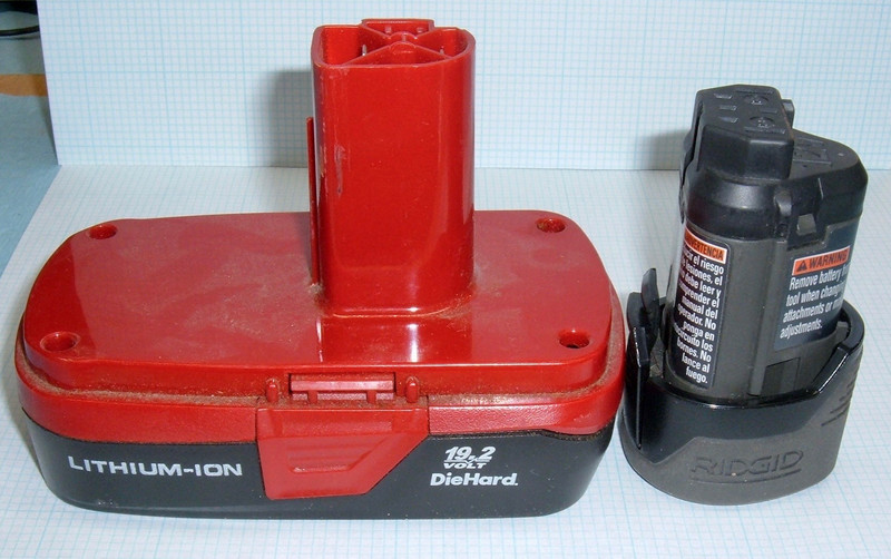

It’s time for more tool battery teardowns! This week, I’ve got a Craftsman 19.2V DieHard battery, and a cute little Ridgid 12V battery. They’re both lithium, and I’m going to dig into both of them, because that’s what I do with old batteries I pick up out of junk bins.

If you’re bored of tool battery teardowns, you could always send me more interesting things to mess with! I enjoy poking around tool batteries, and a lot of the ones I pull apart are “new to the internet” in that they haven’t had a detailed teardown before. It’s always interesting to see how different companies approach much the same problem.
Craftsman 19.2V DieHard 315.PP2011 Lithium-Ion Battery
Say that five times fast!
You can find the OEM packs for about $40 on eBay, with various aftermarket clones for a bit less (including some with a nice capacity bump - buy the 4.0Ah packs if you need one of these and don’t mind some extra weight).
This battery looks to me like a lithium replacement for the old NiCd batteries common in the early battery powered tools. The “stalk” style connection and the larger base are common with the NiCd packs.
I can’t say I’m a huge fan of Craftsman anymore. They used to have the perk of “If you break a simple tool or socket, take it to Sears and they’ll replace it,” but where’s your closest Sears? Can you answer that without pulling up a map application and checking? I didn’t think so.
In any case, we’ve got a “19.2V” battery. That’s a 16S NiCd voltage rating - for a 5S lithium battery, you might call it 18.5V (3.7V * 5), you might call it 21V (4.2V * 5), or… you might call it whatever you want, because marketing decides what to use, and battery powered tools are incredibly tolerant of a wide range of input voltages.

The bottom contains the usual warnings I’m about to partially ignore. Do not open. Right… it’s in my shop as a battery pack, it’s getting opened.
We can see a rated capacity of 24Wh, which isn’t very impressive. The DeWalt 6.0Ah pack claims 120Wh (I’d rate it a bit less, but then I’ll probably disagree with this pack rating as well). It appears the pack model is CS1313. If we use the nameplate 19.2V, 24Wh is 1250mAh per cell. If we use a more reasonable 18.5V rating, that’s 1297mAh per cell (call it 1300).

On the top of the pack, there are 4 pins. Presumably, one is positive, one is negative, one is related to temperature in some way, and… I have no idea what the other is. Something important, likely. Probing around the pins with a voltmeter doesn’t give me anything more than a few dozen mV, so there’s no obvious voltage on them. Either the pack is dead, or there’s a BMS shutting things down until it receives the proper initialization signal. Given that this looks like the pinout for a pre-lithium pack (there aren’t enough pins for the charger to see the per-cell voltage), there’s almost certainly a BMS down in there. If you want to replace a NiCd pack with lithium, you need something to manage the pack, because the tool won’t do it (draining a NiCd pack all the way down is fine, but doing the same to lithium damages the cells - you need a low voltage cutout far above 0V for a lithium pack, and you have to balance the cells during charging).

I do not understand why companies bother with security Torx bits on tool batteries. This pack uses some T10 security bits (they have a little pin in the center). If someone is going to have the proper sized small Torx bits to open the pack, the “security bits” don’t really add much of a hurdle. The pack comes apart easily enough (with some broken screw tabs on one end), and… yup! There’s a complex battery management system in there!

With a bit more fiddling (pull the side latch buttons out first), the whole pack comes clear of the base. Like most modern tool packs, it’s a 5S lithium battery built out of 18650 cells. With a complex BMS on top.
Look at the weird little circle in the nickel strip on the lower right - that’s a basic fuse. The thin strips on the edge will melt if the current gets too high. It’s a perfectly good “Aw, this has all gone very wrong…” sort of failsafe. I’d be surprised if the fusing current was consistent within 50% across a bunch of packs, but it should blow if the whole pack shorts, and that’s the goal.

The Pack Guts
On one end, a pair of IRF1404Z MOSFETs handles switching duty for the pack. These are rated at 75A (each), so they should be fine switching a pack like this. It’s a conservative derating, but it’s what a lot of pack manufacturers were doing at the time. I’m guessing there’s some issues with shutting down the pack under load with a single MOSFET, or that they get too hot with a single one. Since heat is proportional to I^2 (current squared), using two MOSFETs instead of one cuts heat in half (with half the current, each one puts out a quarter the heat, but you have two of them). The center leg is normally connected to the body of the MOSFETs, so they are connected through the heatsink, via the hold-down plate arching over the front of them.

The cells are LGDAHA11865s - 1300mAh, high drain cells (meaning pack capacity was calculated on 18.5V, not 19.2V). They’re rated for 15A sustained, somewhat higher in bursts. That’s not particularly impressive in 2018, but for 2010, these were definitely solid performers. Like almost every other datasheet I’ve seen, this one includes the phrase, “Do not solder on battery directly.“ This set, unfortunately, is at about 0.4V/cell. Well past dead, and firmly into the “I’m not going to recharge them” category. I don’t like letting lithium below about 2.5V/cell, and 3.0V/cell is a better cutoff for normal use.

Fortunately, these aren’t soldered - they’re very nicely spot welded. On top of that, the tabs are held in place with some plastic that’s been melted down to form a little rivet cap - you can see it near the intersection of the T. That plastic cap holds the nickel strip very firmly in place, and combined with the locating nub at the bottom, everything is very precisely located. I’ll assume it’s hand assembled, but with machine like tolerances from this design. Very nice!

On the other side, with a few layers of foam removed, there’s a little thermal sensor. This is the bog standard 10k NTC thermistor that nearly every battery pack has, and while I’d rather see it not against one of the live ends, there’s no indication of wear on it, so the foam padding worked properly to keep it immobile. The actual sensor is potted in a hard black epoxy, so it’s quite unlikely to wear through.

With the BMS separated from the pack, you can see that the two halves of the pack are actually screwed together. This pack design uses a lot more screws than I think is reasonable for a more or less disposable tool pack. Oh well! This one goes to the recycling bin.

The Battery Management System
I’m always curious about how battery management systems function - will they let me draw current off the pack without authenticating somehow? I don’t have a live pack anymore, so I just hooked my bench power supply up. I was able to see the power supply voltage on the output pins, but attempts to draw current from it failed - it just shut down the outputs. I don’t know if I need the pack voltages in range as well, or if I haven’t authenticated properly to the pack, but it doesn’t seem an easy one to use for random projects.

Or, maybe the board is dead and I was seeing voltage leaking through to the output terminals. This bit of corrosion and char was hidden under the output tower. Nothing good happened here. I’ve got no clue what really happened, but the board has obviously suffered a failure of some variety or another in this set of components. It’s possible this killed the pack, or it’s possible the pack still functioned fine. But, this is a complicated BMS that’s suffered a failure.

What, exactly, is the BMS chip? I don’t know. Off the large chip, the part number strings: “TS1102A 1304KM419 100” - and I cannot find references for a chip that looks like this with those strings. The small chip is “C10020 12B23Y” - which I also can’t find.
But - this board is a weird, weird looking BMS. If a pack has external balancing through the charger (each of the cell groups is brought out to the outside), you can get away with a simple BMS that just monitors for overvoltage or undervoltage (on each cell group) and shuts the pack down if something goes wrong. For a pack that doesn’t have external balancing connectors, you typically find a bank of bleeder resistors and associated transistors to allow each parallel group to discharge slightly if it’s too full (or fuller than the rest). You just bleed off the charge from the fullest cell group into a resistor, allowing everything to hit the target charge voltage (typically 4.2V) together.
This pack has neither. There’s no external balancing connections, and there are no bleeder resistors arrays either. Instead, there’s this single large capacitor well secured to the center of the board. It’s a 35V, 100uF capacitor, rated to 105C.
Why might you have a large capacitor on the center of a BMS board? It could be a filter for the electronics power, or this could be a rare charge shuttling BMS. Instead of bleeding off the charge from a full cell group, a charge shuttling BMS will sip off a bit from the highest group (or the full battery), store it somewhere (say, a capacitor), and dump it into the lowest cell group. I don’t know if that’s what’s going on here, as I’m not about to fully RE the board, and I have no datasheets for either of the ICs. But it’s a possibility. If that’s what’s going on… someone needs to be thwacked, because there’s no reason to put something like that in a tool cell BMS! It just doesn’t matter for something this size, but it is the type of thing you might see unchecked engineers doing for fun. For a large electric car pack, it would be reasonable, but for this? You’re just being fancy for the sake of showing off.
Take a look along the top - there are quite a few interface pins as well. I would guess this is a quite capable board, if you find a way to talk to it. I’d wager that SW1 and CL1 talk to some variety of status LED indicator, if you know how to hook things up. With a dead pack, I have no way of testing that, of course.

Flipping the board over, there’s the normal “Don’t charge me backwards” diode that I’m not sure matters with lithium, a design/build date of May 23, 2012, and some genuinely interesting looking routing going on. If you look in the center of the board, the traces all have nicely rounded corners. But, if you look on the right side, and a bit in the lower left, you’ll see hard corners on the traces. There are even some traces where both are going on - look at the first thin trace left from the right edge. The lower bend is rounded, then it has a few sharp 45 degree angles in it. Why is the board half one way and half another? Again, I have no idea at all. Perhaps someone realized that the engineers were making a work of art and told them to knock it off and ship it.

It’s complicated, but this is what you have to do if you want a lithium replacement pack for a tool designed for NiCd batteries. You can’t rely on the tool to do the right thing for lithium if it’s built for NiCd.
Unfortunately, things weren’t working well enough for me to figure out the proper pinout and encodings to turn the pack on. Sorry! If you know, I’d love to hear about it in the comments.
The Ridgid 12V 16Wh CS1031 Li-Ion Battery
Compare and contrast the previous pack with this pack - which is designed as a lithium ion pack, for a tool designed to work with lithium-ion batteries. In theory, these will be cheaper because they’re smaller and simpler, and it looks like they sell for $25 or so.
This is a Ridgid 12V pack, rather obviously (from external appearances) containing three cells arranged in a triangle. This is for small Ridgid brand tools, and… well, the pack is kind of a toy, really, for toy tools. At least by my standards. This thing is tiny, and it goes in things larger than a flashlight. I guess if you just need something for hanging curtains… I’m a big fan of DeWalt, and my teardowns of their packs have only strengthened my opinion of them.
The sides have assorted warnings in multiple languages.

The bottom shows the usual warnings, that it’s a “12.0V” battery, and that it’s 16Wh. Again, I’m going to grumble about their way of describing the pack. You could describe it as a “11.1V” battery pack (3.7V * 3), or perhaps a “12.6V” pack (4.2V * 3). Calling it, specifically, 12.0V? That implies a cell voltage of 4.0V, which isn’t really full for lithium, and isn’t really empty. This pack will range between about 9.0V and 12.5V during use (I’m assuming it doesn’t get fully charged for longevity reasons, which some companies do). So… if you want to call it a “12V” pack, that’s fine, but “12.0V”? Oddly specific, and entirely wrong, IMO. It’s not like they’re fudging voltages to stay under the 100Wh limit for the mail service.

Just in case you forgot it was a 12V pack, the top reminds you. There are also battery terminals, with the + and - terminals helpfully marked. These terminals are a bit recessed, so hard to get at with a probe. Don’t worry, I’ve got the pinout for you later!

Testing the Pack
So far, most of the “designed to be lithium” packs are really friendly for people wanting energy storage outside of plain old tool service (POTS). This pack has voltage on the pins - so I set about testing it as well to see if I could draw some current by cramming wires in the terminals.

Yup! Shove wires in, receive current. Also, ouch. That internal resistance. With an amp of current, I’ve got a 1.6V drop across three cells (implying a total resistance of 1.6Ω). I’m going to guess this is why the pack was tossed. Some of that resistance is in the terminals, but not much of it. Cell internal resistance increases as cells wear out, and this sort of nasty voltage drop tells me the cells in here are shot.

Going Inside
Ridgid decided, for some reason, to hold this pack together with clips. My first step was to remove the bottom grip, which took a few screwdrivers and turns out to have been totally pointless. With the bottom off, the pack is… still totally closed up, and you can see that the plastic forms the bottom of the case. To the top!

The top clips are soft and easy to snap off if you’re not careful. This is not a pack designed to be opened and maintained - it’s designed to be quick and easy to assemble, and then, presumably, recycled. Inside, as expected, there are three 18650 cells. I like the rubber padding at the bottom of the pack - useful for shock resistance.

With the rubber padding removed, you can see the tabs for the bottom connections. The bottom tab has a thick wire heading up the side for the pack negative connection, and the top tab has a smaller wire heading up for voltage sensing/balancing of the pack. Looking at the alignment on the tabs, this is definitely done by hand (and then the wires are soldered on by hand).
If anyone has friends who work in tool battery factories, I’d love to hear some stories. Equipment, working conditions, etc.

The cells are LR1865BEs - not a bad looking cell from 2009! They’re rated at 1350-1400mAh, are a spinel LiMn chemistry (which means cobalt free), should put out 25A, and have a DC internal resistance spec of 25mΩ! The capacity is low, but the rest of the specs are nice.
Since they’re charged, I tested their internal resistances now, a decade later. I got 70mΩ, 100mΩ, and 680mΩ. No, that’s not a typo. Six hundred and eighty milli-ohms. Wowzers. That’s why this pack was in the junk bin - that cell won’t even power a decent flashlight anymore. At 4.2V, it won’t source 6A before the voltage has collapsed to zero (though, at this point, all bets are off with how it actually behaves, and I don’t care to play with something this worn out very much).
I don’t quite understand why the positive lead loops down the side. I assume it’s to provide slack for assembly.

In the very center of the pack, there’s a neat little rubber triangular spacer to keep the cells from banging together. They took their shock protection seriously in this pack, and I’ve got no complaints at all.

The Terminal Block
The top of the pack just pulls off, leaving the set of terminal blocks. Much like the DeWalt packs, the main battery connectors are a double height set of terminals, which makes sense - they need to pass a lot more current.
I pulled an extra little thermal pad off the lower cell to expose the thermistor.
Probing around now that it’s easy to do so, the left two pins in the top row are the inter-pack cell voltages. The left is C1 (voltage after the first cell), the center terminal is C2 (voltage after the second cell). The voltage after the third cell is the main B+ terminal. These connections are used to balance the pack during charging so all cells end up at the same voltage.
The lower center pin is hooked up to the thermistor, with the other end on pack negative (B-). This looks to be a normal 10kΩ NTC thermistor, same as pretty much everything uses. These are easy to test - measure the resistance across them, and put your finger on them. If they’re actually a thermistor, the resistance will drop in a hurry as you heat it up. Obviously, if you’re working in the tropics, this test may not work as well, but I do like my office cold if I’m in there…
Finally, the top right pin is an ID pin - measurement and inspection of the resistor indicate that this is a 10kΩ resistor to B-. I haven’t messed with enough Ridgid tools to know what this actually means to them, but presumably the tool checks it (or the charger checks it) before doing anything with the pack.
And then there’s that weird looking resistor on the left side…

I spent a while with various lighting trying to figure out what other colors the bands on that resistor were, and what it was doing connected to the C1 terminal. I finally decided to search for it, and discovered that a single black band on an axial terminal resistor indicates a zero-ohm link. Which, annoyingly, is not the same as a wire. It’s a resistor with nearly zero resistance, but maybe more (up to some maximum value in the 10s of mΩ range). This is being used as a jumper, obviously, but there’s also the same sort of thing in another sense wire running down the side.
My assumption is that they wanted “some, but not very much” resistance on the sense lines in case someone inadvertently shorted them. It will keep the current flow down, though I’m not sure how long these little resistors will last holding back a short circuit current from these cells. At least, when they were new.

In any case, here’s the pinout for the Ridgid 12V battery pack. Simple, straightforward, and pure lithium!

Final Thoughts
The contrast between these two packs really shows the difference between a pack designed to replace a NiCd pack, and one designed for lithium from the ground up. The Craftsman pack is far more complicated because it’s replacing a very forgiving set of cells. The NiCd packs are just a series group of cells. They self balance, they don’t care (too much) about being deeply discharged, and they’re a simple pack. To replace that interface with lithium requires a good bit of smarts in the pack. Those smarts, often enough, end up being the weak spot.
A tool designed around lithium batteries (like the Ridgid pack, and like the other DeWalt packs I’ve torn apart) doesn’t need anything nearly so complex. It can rely on the tool and the charger to handle the tricky bits of balancing and low voltage cutoff, which leaves the pack simpler, cheaper, and, hopefully, more reliable!
Comments
Comments are handled on my Discourse forum - you'll need to create an account there to post comments.If you've found this post useful, insightful, or informative, why not support me on Ko-fi? And if you'd like to be notified of new posts (I post every two weeks), you can follow my blog via email! Of course, if you like RSS, I support that too.


