
Earlier in 2018, I did some experiments related to the Raspberry Pi 3 thermal behavior under load, and I found a case that worked reasonably well to keep it cool.
What I missed, though, was an even better case on the market that does an even better job with cooling - the FLIRC case. It’s slightly more expensive than the “Moster” heatsink case I used, but it’s a good bit better at cooling a Raspberry Pi 3.
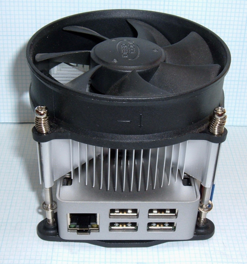
It does a really good job with the 3B+ as well - but it didn’t keep things quite as cool as I wanted. As is often the case in my lab, what started as “messing around” turned into something far more exciting: This contraption! I have no idea what to call it, but it’s pretty cool (running)!

Sure, it looks weird. But it works. My Raspberry Pi 3B+ can build the Linux kernel at 1.4GHz without even hitting 50C! Can yours do that? Plus, the fan is automatically controlled by some software and the GPIO pins - which, in addition to saving a (tiny) bit of power, just looks cool when the fan comes on automatically.
The Raspberry Pi 3B+
On Pi Day, 2018 (March 14, or 3.14), the Raspberry Pi foundation announced the latest and greatest Raspberry Pi - the Raspberry Pi 3B+. This replaced the Raspberry Pi 3, and included a number of very nice improvements - gigabit ethernet, 5GHz wireless, slightly faster RAM, a new power supply on the board, an improvement in processor clock speeds and, most excitingly, radically improved thermal behavior. The board is thicker and heavier from upgraded internal power/ground planes, which helps spread heat, preventing the chip from clocking down as much as on the Pi 3. Plus, there’s the nice mental heat spreader over top, helping cool hot spots on the chip.

The faster processor, though, is a bit of an interesting case. For the Raspberry Pi 3, the processor held 1.2GHz up to 80C, and then throttled back to hold ~80C. For the 3B+, while the processor is rated at 1.4GHz, it will only hold 1.4GHz up to 60C. At that point, it drops back to 1.2GHz, remains there up to 80C, and then throttles much like the old system.
If you’re trying to measure the processor speed on a Raspberry Pi 3/3B+, any of the guides talking about the Linux processor governor are wrong. You need to use vcgencmd. The CPU will throttle independently of what the kernel governor requests.
pi@raspberrypi:~ $ vcgencmd measure\_clock arm
frequency(45)=1400000000
The FLIRC Case
Around the time I picked up the Raspberry Pi 3B+ (Micro Center is awesome), I also decided to mess around with the FLIRC case. You can order from them directly, or find them on eBay for about $18. If you’re lucky, you can find a combo that comes with a Raspberry Pi 3B+ and the FLIRC case together.
It’s a beautiful aluminum case with a nice plastic cover on the top. In addition to protecting the Pi very well, it just looks good. The bottom is plastic, so wireless still works well.

There’s a depression in the top that reaches down to make contact with the processor, which serves to transfer heat to the entire case - it’s noticeably warm in operation, but the processor stays nice and cool, because it has a very large heatsink with a lot of area to radiate heat. The aluminum does a great job spreading heat to the whole case. See those plastic tabs around the edge? Those let you remove the plastic top if you have reason to - which I most certainly do!

What I found, playing around, is that the FLIRC case will cool the 3B+ passively at 1.2GHz, but not 1.4GHz. Temperatures under load rise up to about 60C, the processor throttles back to 1.2GHz, and then temperatures are stable just a hair above where it will run at 1.4GHz. Temperatures won’t keep climbing towards 80C and the more extreme throttling unless the room is really, really hot. But, neither will they stay cool enough for 1.4GHz unless the room is really, really cold.
Screwing Around
I don’t know what you do when you’re bored and it’s smokey outside so you can’t do much property work, but I’m inclined to play around with kernel builds and thermal throttling - or, at least, I was a month or two ago.
Just how good is the thermal connection to the case? How much heat can I really pull out?
I started messing around assuming that, eventually, I’d bolt a peltier cooler on somehow to keep things as cold as I wanted them. My goal, for no particular reason, was to sustain 1.4Ghz. Why? Because I figured I should be able to do that. Even if it required peltiers. I’ve got this extra performance, and I enjoy wringing out devices like that.
With a kernel build churning along (I spend more time than most building kernels on my Raspberry Pi boards) and the top plastic off, I figured that some water would cool the cores down. I literally poured some water into the indentation to see what happened.

The results? CPU temperatures dropped a few degrees - enough to throttle the chip back up to 1.4GHz! This lasted for a minute or so, then the water heated up enough that it stopped doing anything useful and the clocks dropped back down.
It demonstrated that cooling the case down would cool the CPU (which should be the case but isn’t always guaranteed), but unless I’m going to put the thing under a waterfall, it didn’t seem terribly useful.
Next, looking around my office, I spotted the “junk” load bank from my Tale of Two Load Banks. It had a big heatsink on it, and it’s such a piece of junk that I’ve been gutting it for parts. The heatsink is a part, so I grabbed it and set it on top of the case, expecting a gag photo out of it before I got to serious work with peltiers. I may have been inspired by a similar gag photo on the Raspberry Pi subreddit a while back.
With nothing but the heatsink sitting loosely on top of the case, the temperatures started down - substantially! The dropped below 60C, and sat there. I let the heatsink sit on the case for a while to see what would happen as it warmed up, but the temperatures stayed low. Enough heat was flowing from the case to the heatsink to handle the chip building a kernel at 1.4GHz - without any sort of thermal grease or the fan!
Well, I know a thread worth pulling when I see one! Some test fitting indicated that I could actually use the heatsink hold down (compressing the springs almost all the way, but… hey, it fits). I grabbed a bit of Arctic Silver 5 (about $5 on eBay) to help the thermal connection to the case. I learned about Arctic Silver nearly 2 decades ago, trying to push some Pentium III 650s to 866MHz with a bit of scotch tape (pin A14, if you care - with that not grounded, the motherboard would read the chip as needing a 133MHz front side bus clock instead of 100MHz). Arctic Silver was the difference between not booting and being rock solid for years. With the heatsink in place, I grabbed one of my “USB to 5V pins” adapters (I have weird adapters like that laying all over my office - this one was a cheap USB cable I’d hacked up for something or other) and hooked the fan up - which proceeded to start spinning!

I didn’t know if it’s a USB current spec violation or not (later investigation reveals it’s not), but it worked - this particular 12V fan will turn, almost silently, at 5V, and will self start properly. With all this in place, I loaded the system up and didn’t even see 50C! No peltiers needed!
Overclocking - Probably Not
With temperatures under control, I decided to mess with overclocking for a while. I was able to successfully run at 1.5GHz - but only if ambient temperatures were below about 70F, and even that required an extra 0.1V of core voltage. Above that, I’d either see compiler segfaults during kernel builds (“A thing that’s definitely not supposed to happen”), or the system would just lock up under load. Unfortunately, at least on my 3B+, 1.5GHz is not stable above about 50C at the chip, and this contraption won’t maintain that in warmer ambient temperatures. Even if it can, barely, run at 1.5GHz some of the time, that’s just too close to the edge for my purposes. I’d rather have something stable than an extra bit of performance - at least for a “daily driver” type computer.
Toss some extreme cooling on the 3B+, and I bet you can find another few hundred MHz. I might just try this some day, but, for now, the extra headroom is going straight to the 1.4GHz base clock, and the chip is running awfully close to the edge as-is.
GPIO Based Fan Control
The only problem left is that the USB cable to run the fan is sort of ugly, and it’s not really controllable. The fan is awesome, but there’s no need to run it most of the time. I may as well save the power, the dust, and the wear and tear on the fan bearings - it’s not a high end fan. Alternately, that’s total post-hoc justification and I did this because it just sounded like a fun little project. You decide!
It’s easy to write a script to determine when the fan should come on, but that assumes some way to interface with the outside world. Fortunately, the Raspberry Pi has a whole row of GPIO (General Purpose Input/Output) pins, and I can use one of them!
I need 5V for the fan, but the GPIO pins are only 3.3V - and not good for very many mA either. However, in my office, I keep a drawer full of MOSFETs for situations exactly like this. The IRLB8721 (datasheet) (eBay) is a great little N channel MOSFET (low side switching - you switch the ground line, not the power line) that will work with signal voltages as low as 2.5V - the 3.3V IO on a Raspberry Pi is no problem for this handy little gadget.
The FLIRC case doesn’t leave room for a daughterboard, but it’s not exactly full. I’ve got a drawer full of 0.1” pin headers of various sizes, so I can just freeform solder a few things up and toggle the fans.
First up, a filter capacitor on the 5V rail. This 1500uF unit goes between the 5V pin and ground, and if it looks oddly like the ones I used to repair an old mainboard, well… I believe in ordering more stock than you need. It’s a 6.3V rated unit, so has a reasonable buffer from USB voltage, without being excessive. A similar sized capacitor rated for 30V would be far, far lower capacitance, so it’s worth keeping caps around in multiple voltage ratings. This isn’t strictly needed, but I’ve gotten into the habit of putting filter capacitors on voltage rails when I start messing with them, and it won’t hurt anything.

Next, I’ve soldered my MOSFET to a two pin header after bending the legs in to fit. There’s a ground pin right next to GPIO26, so I’ll use that pair. The top pin here is the source pin, which goes to ground, and the bottom pin is the gate pin, which connects to the GPIO pin. The center pin is the drain, which connects to the negative lead coming off the fan. Touching the metal back of the MOSFET isn’t a problem - that’s also the drain. Fun with lightweight hardware! There’s no reason not to do this sort of stuff for one-off proof of concept builds, but hold the pin leads in a pair of pliers while you’re bending them in. They rip out of the bottom of the MOSFET more easily than one might expect.

Solder on some wires (5V on the yellow wire, the black wire goes to the switched ground), strip the ends to fit in the fan connector, and I’ve got a working GPIO switched fan! The left side of the header has a pair of 5V pins on the end, then a ground pin. The capacitor goes between the end 5V and ground, and the yellow wire comes off the second 5V pin. All of this fits nicely in the case without touching anything.

I then wrote a handy little bash script that monitors the temperature and turns the fan on and off. To avoid rapidly switching the fan on and off, I include some hysteresis - the fan comes on a 45C, then remains on down to 40C. Using the GPIO pins from the shell isn’t the most obvious thing on the planet, but it’s easy enough once you learn the incantations, and more than fast enough for this use case.
As root, you need to enable the interface for the proper pin, set the direction, and then you can toggle the GPIO on and off, which controls the MOSFET, which controls the fan!
echo 26 > /sys/class/gpio/export
echo out > /sys/class/gpio/gpio26/direction
echo 1 > /sys/class/gpio/gpio26/value
With the fan wires run out the lower IO pin gap (the FLIRC case doesn’t prevent you from snaking a cable out), I have a fairly tidy install. I could make it cleaner by cutting the connector off and passing it through one of the holes in the top, but I don’t care that much, and I’d rather keep the stock fan connector in place.
The fan mounts fairly cleanly to the case, and if you have the alignment right, you can even access the SD card without any fiddling. It almost looks like it’s designed for the case!

You can see where the heatsink sits - right next to the processor divot. I wouldn’t have assumed this would make the sort of difference it does, but… well, the results don’t lie! I’m able to pull off enough heat to keep the CPU around 50C under typical real world loads!

Power Draw Numbers
I went into this bit of tweaking using some numbers I’d found on the internet for 3B+ power draw - which were, shall we say, “optimistic.” I prefer the description, “complete and utter crap.” I’ve yet to see anyone report a total system consumption above 1A, but a comprehensive test (including most pessimal code for power draw) will get nearly double. There’s this little gem called “cpuburn-a53” that just thrashes the Raspberry Pi SOC and makes it draw an absurd amount of power, and linpack is just as bad. “Playing a video at the desktop” is mildly interesting, but if you’re going to report the maximum power draw of the 3B+, report the maximum power draw. Which is over 2A.
Since I’ve been struggling with voltage drop, I set up my DPS6015 bench buck converter with a USB out adapter, plugged a USB current measuring device in, and went to town measuring current draw in various situations. This lets me jack the voltage up to avoid brownouts at the Pi.

I tested at the stock 1.4GHz and at my 1.5GHz with 0.1V overvolt, including after the chip throttled back (only with cpuburn - the thermals are fine with normal loads). My “realistic load” was a kernel build - this is harder on the system than the normal “run yes a lot” loops you see for “stress.” CPU load was pegged at 100% for the tests.
My fan draws 80mA at 5V, and I’ve removed this from the power consumption numbers because it’s only relevant to me. My idle draw includes a KVM hanging off the Pi and 5GHz wireless connected, so the idle use is a bit higher than some people see, but the offsets should apply to just about everyone.
The “/K” lines are kernel builds, “/C” are CPUBurn, and the “OV” indicates the overvolted condition.

Yeah. Nearly 2A with stock clocks, over 2A with a minor overclock/overvolt. Plus fan, for me. This is a power hungry beastie, and you really, really need a good power supply for it or you’ll get brownouts (which drop the CPU clocks back to 600MHz). The reason the FLIRC case can hold 1.2GHz fine but not 1.4GHz is obvious here - there’s a huge step in power consumption (and heat dissipation) between 1.2GHz and 1.4GHz. But, seriously. Raspberry Pi reviewers need to wrap their head around what “maximum power draw” actually means, and report that. I really, really didn’t expect to see 2A into this board based on what I’d read.
Final Thoughts
I genuinely didn’t expect tossing a random heatsink on top of the FLIRC case to make a large difference - but it did! It’s the sort of result I enjoy finding from messing around. Having a fairly well equipped office makes a big difference in this sort of discovery. I wouldn’t have gone out and purchased a heatsink for testing this - but a junk heatsink, sitting on a load bank I will never again apply power to (it likes to short the load, which is kind of unacceptable)? Sure! I’ll mess with it!

Why do I care so much about thermals for the Raspberry Pi? Earlier this year, I posted some progress on something I called “Pi3Desk” - using the Raspberry Pi 3 as a light service desktop. I’ve continued developing this project, the 3B+ has some nice improvements (5GHz wireless is fast enough to be useful, plus sustained 1.4GHz is awesome), and next week, I’ll be talking about my revisions and improvements - and, as was requested a lot last time, I’ll be including the steps to take to actually make your own Pi3Desk++ (starting from a base install image)!
Plus, I’ve corrected wrong information on the internet. The 3B+ is incredibly power hungry, and you should design for that.
Book Review: The Long Way Home by Ed Dover
A couple months ago, I shared some articles talking about the Boeing 314 that flew from New Zealand to New York - going west, through uncharted territory, and flying over an awful lot of land. It was a great flying story then, and if you liked it, you should read this book. It’s a fairly short book, and an entirely enjoyable read about the trials of navigating a flying boat, that can’t land anywhere but water, through uncharted territory to get it home at the start of WWII’s hostilities in the Pacific.
It’s a tale soaked in 100LL, 90 octane autogas, salt water, an amazing airplane, and a crew that, told to do the impossible, simply sat down and figured out how to do it (and raided the local library reference desk for whatever maps the could find). I love reading stories of what people can do when they’re put in “impossible” situations, and this delivers.
It’s not Fate is the Hunter by Gann, but it’s a story that should absolutely belong in that collection!
Comments
Comments are handled on my Discourse forum - you'll need to create an account there to post comments.If you've found this post useful, insightful, or informative, why not support me on Ko-fi? And if you'd like to be notified of new posts (I post every two weeks), you can follow my blog via email! Of course, if you like RSS, I support that too.


