
Another week, another gizmo to analyze. This week, I’ve got a DPS6015A buck converter on my bench - and it is good! This is a much fancier unit than I normally deal with here - it’s about $70 on eBay. But, it will convert from an input voltage of 15V-80V to an output of up to 60V/15A/900W.
I make extensive use of these in my office. I have one for running my lighting (and eventually my low voltage DC bus), and I have another one that I use as a bench power supply for precision work (my analog bench supply isn’t amazingly precise). Since these handle up to 80V, they can work directly from my battery pack - my pack will be up over 60V in the winter when cold, which means most cheap buck converters aren’t rated for this (and I don’t believe in exceeding the max rating on power electronics). So this is a great unit for my office - and a great unit in general.

On top of that, it’s got serial ports! This unit has a TTL serial port, a RS232 serial port, and a RS485 serial port! You can entirely control the unit over serial, which is exciting - and, until next week, entirely undocumented (at least in English).
So, how do you use this thing, and how accurate is it? Keep reading!
The DPS6015A Buck Converter
The DPS6015A is one of a series of digital buck converters from MingHe out of China. I’m increasingly familiar with their hardware, because they build an awful lot of stuff I find very useful in my line of work - buck converters, boost converters, solar charge controllers, etc. I’d love to meet someone from that company, if they ever happen to find this blog…
For DC power, a buck converter is a power converter that will drop voltage (and increase amps). This is the opposite of a boost converter (which raises voltage). If you get really fancy, you can find a boost/buck converter, but they’re rare (and usually expensive).
This unit will take an input voltage of 15-80V, and can provide an output voltage of 0-60V (assuming the input voltage is high enough - the output voltage will never be above the input voltage).
Yes, it’s awesome - and, for $70 on eBay, it’s an amazing deal for a very accurate unit (if not quite as tight as the spec sheet claims).
As delivered, the unit comes with the display attached to the main power board - but this comes off easily enough if you want to control it purely over serial or use the (hopefully included) longer cable to separate the controller from the guts of the unit.

And, as is usual for multi-layer devices I review, I’ll start by pulling the unit apart to get to the good parts. This unit has some very, very exciting parts indeed!
With the user interface removed, the board shows off it’s stuff. This is a high quality board (as might be expected from the price), and I have no complaints about the construction or soldering.
The beeper is visible slightly left of center, and is used for keypad feedback as well as alerts (if the board is over temperature).
The terminals in the top left corner are the input, and the terminals on the right side are the output. They’re screw type terminals, so you can get a solid connection with the wire. With an output current of up to 15A, you’ll want good connections to avoid excessive heat.

Roughly center in the board, on the bottom, the four sided IC is the main processor for the unit. This is a STM8S005K6 - a little 16MHz microcontroller with 32kb of program storage, 2kb of RAM, and (importantly for a device like this) 7x 10-bit A/D (analog to digital) converters. The A/D converters are voltmeters, allowing for precise reading of voltage and current through the device. It’s comparable in many ways to the Atmega 328s used in the Arduino Unos.

Flipping the board over, the quality continues. I hate to say I’m a bit of a MingHe fanboy, but I’ve not yet run across one of their units I don’t really like, and I have several hundred dollars of their stuff in my office.
All the thick traces in the top left are the high current bits - the input jack is at the top right, and the output jack is the lowest pair of terminals in the left side. Power conversion circuitry is actually really simple, if you ignore the control systems for them! Some switching transistors, an inductor, a few capacitors…
Another thing to point out here is that the right side of the board (the communications corner) has a separated ground plane. See the line around the lower right corner (well, most of the right side)? This is how you separate sensitive systems (like your serial control bits) from high power electronics controls that may be pumping enough current around to disrupt the ground plane somewhat. Separate ground planes are suggested for many things, but rarely seen. I’m impressed.

Zooming in, the lower left corner of the board is most exciting indeed! This is the communications corner - and it’s quite complete. I’ve said before that anything interfacing with reality is likely using serial at some level or another, and this unit is no exception. The 10x2 pin connector in the lower right is the display connector. The 5x2 connector to the left is a TTL serial connector (and I’m documenting the protocol next week). But, it keeps going. The lower left connector is an old-school RS232 serial DB9 connector (some of you may have connected mice or modems via these connectors). And above that is a RS-485 connector! This is a differential serial connection that supports multiple devices on a given bus and insanely long transmission lines. I’ve written about it before in the context of the DMX stage lighting protocol, and I’ve also visited a greenhouse facility that had all the industrial control systems in each greenhouse linked together to a central monitoring station with a long RS-485 run. This is a serious serial powerhouse - and I’ll dive into the serial bits later, to avoid disrupting the main board overview too much.

Moving up on the board, the top left corner contains a power switch, the “SW” pin header, and the input terminals. The switch and the SW header will both power the board on. Short the SW pins together to power the board on if you have some need for external control. Be careful if you’re doing this with a high source voltage - the high side switch pin terminal is receiving the full input voltage, so be sure you design for that.
The 34063 is a DC-DC converter control IC, next to the little power transformer.

The lower right corner contains some inputs if you want to use an external voltage sensor, and/or to control the current/voltage limits with analog voltages (0-5V, if I read the manual properly). I haven’t messed with these because I haven’t found good documentation on them, and they’re not useful controls for my use. If you know how to use these, please, comment below!

The heatsink contains the switching gear for the power conversion circuitry. On the left, a 045N10N 100V MOSFET (for an 80V rated unit - that’s very reasonable to me). On the right, a STPS20H100C 100V Schottky rectifier. What the heck is a Schottky rectifier? They’re a very fast (~100ps response time), very low forward voltage drop diode that’s commonly used in switch mode power supplies (which this is).

The other side of the heatsink is dominated by the inductor and a few filter capacitors for the input and output sides. Plus a nice resistor. While the capacitors on this unit are in good shape, I’ve started to notice a tiny bit of crud on the capacitors on my lighting power unit, which has been in service for about a year. You may have to replace the capacitors on this unit at some point, which is annoying, but not really that big a problem (and only with very heavy use).

Finally, right by the output terminals, there’s a 1% tolerance 0.005Ω resistor - a current sense shunt. For those unfamiliar with how you measure current, it’s rare to measure current directly (you can do it with the magnetic clamp on meters or hall effect sensors, but they only work well at higher currents). In a device like this, current is measured with a shunt resistor. The resistor does the whole resistor thing, and creates a voltage drop over the resistor based on the current, subject to Ohm’s Law - V=IR. For this resistor, a current of 1A would lead to a voltage drop over the resistor of 0.005V (5mV), and the full 15A output would be a drop of 75mV.

While the board can work perfectly well without the user interface daughterboard connected, most people will leave this board on. It contains the display (a standard enough 16x2 LCD), a few LEDs, a rotary encoder, and the 10 buttons.

Flipping it over, the 20 pin ribbon cable is visible, and it’s clear that this board has nothing “smart” on it (besides the LCD driver IC). It’s just straight connections to the various buttons and pins, with the LCD being driven via the normal set of pins that drive a cheap LCD. Conveniently, this unit comes with a longer flex ribbon if you need it! If you need an even longer remote mount, a standard 20 pin ribbon cable should be fine, though I have no idea how long you can drive the signal before it fades out. For long range control, serial is the right answer.

Basic Operation
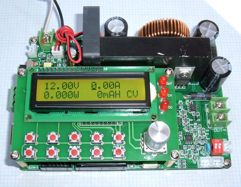
When the unit powers on, you’ll see the basic “set the limits” screen. If you’ve got factory defaults (you should), the unit will power on with M0 loaded (0V/0A), indicating “OFF” in the lower right corner, with no LEDs lit.

The rotary selector (and the up/down buttons at the left of the bottom row) will move you through menu settings, and the top row of buttons will load up presets M1-M4 (with the “F5” button doing nothing). The “M” button in the middle of the bottom will also scroll through memory presets.
The “SEL button will toggle the cursor between no entry (where it starts), voltage, and current. It will underline the digit you’re changing, and the left/right button will change which digit you’re changing. It overflows properly (so 0.09 rolls over to 0.10 if you’re working on the last decimal place), but there’s a wide range of voltages and currents you can set, so use that to dial the value in quickly. Change a digit with the rotary selector, or the up/down buttons.
What you’re setting here are the maximum values for voltage and current allowed. The system will run on whichever limit it hits first, and will indicate on the right side which one is in effect. This is standard behavior for a programmable power supply, so it’s nothing unusual here you have to worry about.
To turn the output on, hit the “OUT/OK” button - bottom right. The screen will then change to the “running” display. This display shows you the current voltage, current current, current watts, total mAh out, and CC or CV to indicate if it’s in “constant current” mode or “constant voltage” mode. The OUT LED on the right side will light up, and the CC/CV LED will light as well (sort of visible here - trust me that the top two are lit up).

With the output on, you can change the voltage or current settings. Use the SEL button to pick the voltage or current to adjust, use the left/right arrow button to select the digit, and then the rotary selector or the up/down buttons to change the value. While you’re changing the value, it will show the new set value, and when you’re done, it waits a moment and then goes back to showing the current output value (this is often slightly different from what’s set, and you can calibrate the unit, but it’s not always perfect in the points between calibration - I wouldn’t mind better feedback loops here).
While the output is on, the top buttons still load memory settings and apply them. You may not want to do this, as putting 60V through a 3.3V component is unlikely to end well.
Be careful changing the settings while the output is enabled, because you can easily fry something if you accidentally change the voltage. Once you have things where they should be, you can tap SEL a few times to hide the cursor (it won’t be under anything). At this point, you can’t change the settings (easily), but you can see a few more bits of data. If you tap the lower left (up arrow) button, the lower line will toggle between the default watts/mAh display, a “time on” display, and the T-SNS display, which shows the current temperature of the switching electronics on the board. Useful! Once you’ve switched the bottom line, SEL will still move the cursor around to change the voltage and current settings, so you can leave the display on whatever you prefer.

Menu Options
On the “not running” screen with neither voltage or current selected, the scroll wheel will select menu options. You can also select options with the “up/down” arrows on the left of the bottom row - either way works the same. The “OK” button enters/selects, and normally either the scroll wheel or the SEL button changes the setting. Some of the menus have sub-menus in them.
SET U-CAL
This is the voltage calibration menu. I’ll talk more about this later.
SET I-CAL
This is the current calibration menu, which I’ll also cover later. In general, don’t mess around with these if you don’t have good bench instruments to calibrate against.
SAVE CAL DATA
Once you’ve calibrated the unit, use this setting to save the new calibrations to the non-volatile memory. If you don’t, your fancy new calibrations will be reset on the next power cycle.
System Recover
This is a factory reset of the unit, including calibration data. Use this if you’ve managed to screw up the unit, but if you don’t change anything without understanding what you’re changing, it’s reasonably unlikely that you’ll screw the unit up too badly. This does restore the factory calibrations, which are good, but not great.
Set SYS.options
This menu contains a few options that you may wish to set. Press OK to enter the menu. Once you’re in, the up/down arrows or the scroll wheel select options. The SEL button changes them, and OK saves the new setting.
Start-up: On/Off
The start-up option determines if the unit powers on with the output enabled or disabled. If you’d like it to always bring the output online when it powers up (I have one driving my shed low voltage DC bus for lighting), set this to “On.” For a general bench power supply, it’s far better to leave this off to avoid inadvertently powering something you’d rather not juice by mistake. If you do have this set to On, the M0 settings are what will be applied at power-on (so save your voltage/current limits to M0 and you’ll get them when the unit powers up).
Sound Enable: On/Off
Do you like the beeper? If not, set this to off.
Fast Falling: On/Off
This setting relates to how the unit handles reductions in the set voltage. If this is set to off, the unit will stop supplying power if the voltage is above the set point, but it won’t actively drive voltage down to the new setpoint. With my bench meter connected, and this off, it takes about 8 seconds to drop from 30V to 20V. With this on, the drop is nearly instant (0.1s or so).
If you have standard bench loads connected, there’s no harm in leaving this on - it’s pretty convenient. However, if you’re using this unit as a battery charger, or have a large capacitor bank attached, turn it off. If it’s on, this will drain the battery bank or capacitor bank through the unit, potentially damaging it, if the set voltage drops below the current voltage on the load terminals.
As a concrete example, let’s say I’m charging a lithium battery bank with this unit. I’ve got a 10S setup, so 42V fully charged. I run it up there in the winter, but in the spring, with more power available, I decide to be nice to the lithium bank and back off my charge voltage to 40V. If I have fast falling on, this unit will attempt to drain the bank through the unit to bring the voltage down - and that’s likely to end poorly for the unit. So this would be a reason to set Fast Falling to off.
There’s enough filter capacitance on the output with nothing connected to see this in action. Turn it off, set a high voltage, and then rapidly drop the voltage down. You’ll see (on the LCD) the voltage slowly following down. If you turn Fast Falling on, the voltage drops immediately.
LRC Enable
This enables or disables the LRC byte checking (a checksum byte appended to commands) for the serial interface. The unit always emits an LRC byte in responses, but this controls checking the byte on commands sent to the unit. If you’re not controlling the unit over serial, well, it doesn’t matter. If you are, you should probably have this on. This helps prevent transmission errors from applying nonsense voltages to loads.
Set Address
Also related to serial communication. You can set any address from 1 to 99. This is needed to address individual units on a shared bus (say, a RS485 serial bus). Unless you’re doing something like that, leave it at 001.
Set BaudRates
Again with the serial settings! You can select the serial baud rate. The default is 9600, which is a good default. Options: 1200, 2400, 4800, 9600, 19200, 38400, 57600, 115200. So, pretty standard PC baud rates and nothing like weird microcontroller rates (yay!).
Set FAN start up
See the fan on the board? You can control the temperature it starts spinning! If you enter this menu, you’ll see the current temperature readout (presumably for the heatsink), and can configure the temperature at which the fan starts spinning. The default is 60C. I don’t see any real reason to change this from the default, but you can change it from 20C to 120C.
Set OTP Value
Capitalization consistency is not their strong suit in the actual menu items. Oh well. The power electronics are pretty solid. This controls the Over Temperature Protection threshold (you might want to have the fan come on below this point). The default value is 120C, and you can set it from 50C to 150C. When the temperature is hit, the unit shuts down and beeps, very loudly, until the temperature drops below the OTP setpoint.
Set Max Voltage/Max Current/Max Power
This trio of settings lets you specify the maximum voltage/current/power (in watts - volts times amps) that the unit can output - helpful if you want to avoid frying something important. The left/right arrow button selects the digit you want to change, for larger changes.
Unfortunately, on my unit, the “Max Power” setting is off by a factor of 10. You set 1W, it limits output to 10W. You set it to 50W, it limits power to 500W. So this feature, at least on my firmware R 2.2 as shown at powerup), is not very useful. Just be aware of it. Max voltage/max current work as expected.
Save Settings to -M0-
If you want to save a voltage/current limit to non volatile storage, use this setting. M0 is the “power on” setting, so if you want the unit to power on to some particular setting, you’ll save a setting here. The left/right button selects which setting you want to save to (M0-M9), and OK saves it there.
Accuracy - Voltage
With all the operating details covered, it’s wise to now see how good it is. If the voltages are all over the place, and you request 5V but it sends 7V into a device, it’s still useless.
The voltage regulation is specified as 0.5% + 10mV (0.01V) - so I set out testing that. I used my bench meter, which is a nice BK Precision 5491B - a high precision unit, though I need to fix some of the higher voltage range calibration on it.

I first ran through the voltage calibration as-shipped, and calculated out the percent error. Out of the box, the unit kept within +1%/-0.25%, though the sudden shift at 50V is where my meter switched ranges and there was a 0.15V shift responsible for that error - that’s my meter, and I need to send it in for calibration at some point soon (the 500V range is off by a hair, and my local calibration shop can’t actually calibrate this unit).
This is without giving it the +/- 10mV slack. If add that, it’s within spec, except for one point. Drat. At 5.5V requested, it’s putting out 5.550V, against a maximum allowed of 5.375V. Still, pretty solid.

After I went through the voltage calibration routine, I ran the sweep again - and, wow! Definitely within 0.5%, and if you ignore the jump from my meter range switch, within 0.1% from 10V on up. Impressive! It’s within spec without even having to add that 10mV bit! The voltage regulation on this unit is solid. I’d love to know what’s going on at the bottom end, but very minor offsets there translate to a high percent error. Still, absolutely meets spec.

Accuracy - Current
The voltage accuracy is excellent, but the current accuracy is less amazing. It’s good enough, but it’s not nearly as tight as the voltage regulation. Spec is 1% + 5mA, and it doesn’t always make that.
I first measured the current accuracy with the factory default settings. it’s almost always on the high side, and is mostly within about 5% (ignoring a bit of error at the very low current settings). Even if I give it that extra 5mA, it’s not within spec… well, much of anywhere, really. At 0.1A requested, actual current is 0.1115A, which is outside the limit of 0.106A, and at 15A, 15.66A is well outside the limit of 15.155A.

Next, I calibrated the unit. After calibration, I collected the data again, and… huh. The low end is awful (50% high at 0.1A - 0.15A is not within spec), and the rest is a good bit better. At very low currents, the unit seems to bolt an extra 0.05A ton, which is where the error comes from (0.05A/50mA is 50% of 0.1A). As the amperage increases, this goes away and the unit works more accurately.

To get something more useful, I zoomed in the graph on the current above 1A. From 1A to 15A, the current accuracy after calibration is much, much better. It’s within -5%/+1%, which still isn’t within spec, but it’s better. In general (or, at least, for my use cases), the current limit is going to be to avoid destroying a device, or to regulate the current through some sort of load that will draw a lot of current, and if one is to err, erring on the safe side is better. So, as long as you’re not relying on the absolute bottom end, current accuracy is decent enough. Still not within spec. Sorry, MingHe.

How To Calibrate
I don’t really care so much about out of box accuracy, though it’s nice to have. What I care about (at least for my high precision instruments, of which I consider this one) is the ability to calibrate them. This unit, after calibration, is pretty darn good (though still not exactly within rated spec). You can independently calibrate voltage and current - and you should do this, if you’re dealing with anything sensitive.
To enter calibration, scroll on the menu until you get “SET U-CAL” or “SET I-CAL” (I think it should be a “V” instead of a “U”, but… maybe that’s their font). Press OK to enter the calibration with your multimeter hooked up properly - voltage or current reading. You’ll need something that can tolerate up to 8A for the current calibration, so you may need more than a cheap handheld meter (though you shouldn’t be calibrating this at all with a cheap meter, since factory calibration is useful).
You’ll also need the unit attached to a 40V or greater power source, because one of the calibration steps is at 32V, and you want to be above that by a good margin on the input side.
The S0/S1 fields set the voltage or current output, and you’ll alternate between them until both are correct (changes to one impact the other one slightly). As long as you make any change on either setting, you’ll keep alternating between them. Adjust both as needed until you nail the calibration per your multimeter - what the display shows doesn’t matter.
After you press OK on both S0 and S1 without changing anything, you’ll get S3 and S4 calibration. These only impact the display on the unit. Set the calibration so the unit displays what you’re seeing on the multimeter. Like S0/S1, this will toggle back and forth until both are solid.
Now, there’s one more important step. After you’ve calibrated the unit, scroll in the menu to “SAVE CAL DATA” and press OK. If you don’t do this, the calibration won’t be saved, and it will reset to the previous values on next power on!
If you’ve completely hosed the calibration and just want to start over with factory defaults, the “System Recover” option is what you want. This restores the factory defaults, including the calibrations.
Voltage Calibration
Voltage calibration is done at two voltages. For S0, set 32.000V, and for S1, set 2.000V. Once those are dialed in, S2 sets the readout at 32V, and S3 sets the readout at 2V. Set them properly and you should be solid on voltage.
Current Calibration
This one took me a bit to figure out, because it was so far out of whack when I got my unit.
For S0, set 8.00A (mine was nearly 8.5A when I got it). For S1, set 1.00A. It takes quite a bit of adjustment to see an impact in these readings, so keep twisting (especially in S0).
Then, S2 sets the display calibration at 8A, and S3 sets the calibration at 1A. Enjoy!
The Serial Interfaces (Finally!)
Finally, let’s dive into the most exciting feature of this unit - the serial interfaces. The console interface is well enough designed and works well, but the true magic of this unit is the trio of serial interfaces you can control the unit from! It comes with a TTL serial interface (5V signaling), a vintage RS232 interface, and a RS485 interface. You can operate the unit entirely from these interfaces, see the current operating parameters, and lots of other stuff. You can’t calibrate it over serial, which I consider a reasonable decision, but anything you’d want to do at runtime? Fair game!
An important note here: All the serial interfaces are connected together. They are not independent interfaces, which means that you’ll see the same data on all of them. Consider it three physical interfaces to a single logical serial port, and hook up one port at a time. If you really, really feel the need to hook up multiple ports, you’ll see the data from the buck converter being transmitted on all of them, and you might be able to control it from all of them, but at this point you have fighting drivers, and that’s just not a good plan.
TTL 5V Interface
The first interface (and the one I find most useful) is a 5V TTL serial interface. This is exported over a 10 pin header (which is quite, quite excessive for the interface), with an entirely undocumented pinout - I couldn’t find it in any of the manuals, even the Chinese ones.

But, fear not! Do you really think this blog would tease you with a serial interface without having figured out how to use it? Of course not! For, what I believe is the first time ever (at least in the English corners of the internet), here is the pinout for the TTL interface of the DPS 6015A and related buck converters! You’ve got a whole row of ground along the bottom, 5V on the top right and top left pins (which are connected together), and then Transmit (TX), ground, and Receive (RX) in the center. Remember, when you’re hooking this up, the transmit pin of your controlling device goes to the receive pin of the device, and the reverse is true. All the ground pins are hooked together, so there’s nothing fancy hiding on them. And, notably, there’s no flow control here - but for the size of transmissions used to control this unit, it doesn’t matter much.

DB9 RS-232 Interface
The next interface is the RS-232 interface - the old DB9 serial port you’ve seen on old computers. Ancient computers used a DB25 port, if you’re curious. The DB9 port is the one on the right, and is the same external size as a VGA port, but the pinout is different (VGA has three rows of pins).
If you deal with a lot of electronics, a USB to RS-232 adapter is useful to have around, and I’ve verified that this port works properly. If you want a real FTDI adapter (and not a fake), I’d suggest SparkFun’s cable.

The RS-232 interface is driven by a SP3232EEN chip - a handy little TTL to RS-232 converter chip. It builds the proper voltages internally, as the RS232 serial protocol uses positive and negative voltages to signal. While TTL would use 0V and 5V, RS-232 uses +/- 3V-15V, so you need to drive a negative voltage (as 0V is neither asserted or deasserted, and is meaningless). This handy little chip does what you need for that - and it also inverts the signal, as RS-232 is “backwards” compared to TTL. For TTL signaling, a logical 1 is high (+5V here) and a logical 0 is 0V. For RS-232, a logical 1 is indicated by negative voltage, with a logical 0 being positive voltage.

RS-485 Interface
Finally, the three connector screw terminal next to the DB-9 port is the port for RS-485 serial. RS-485 is an industrial serial protocol, with differential signaling that works better on long runs and high noise environments. It uses three wires (A, B, and a ground/common reference), and can optionally be terminated (required on long runs). This board supports 120Ω termination, which can be set by the jumper just behind the connector.

There’s a 75176B chip sitting near the port. What is it? A differential bus transceiver - exactly the sort of little chip you’d want to run a RS-485 link!

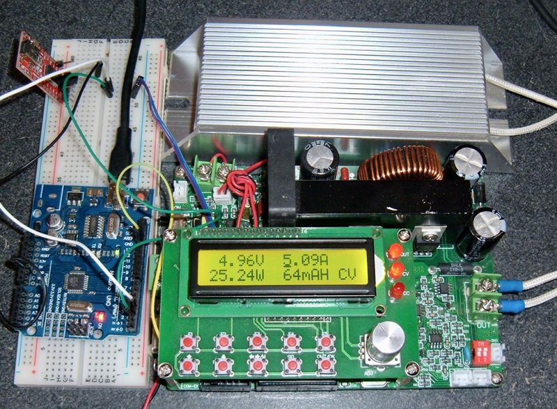
Using the Serial Interface
Now, how do you actually use the serial interface? Well, that’s next week’s post (plus a matching Arduino library). The information is out there, but it’s not at all easy to find, and, of course, nobody has written any of it into a library.
Final Thoughts
If it hasn’t come out through this review, I really like this little unit. Even without the serial interface, this is a unit that’s absolutely worth the money. As I said, I use them in my office, since they work with the main battery pack charging voltage in the winter (up past 60V), they’re accurate, and they’re easy to use. I wouldn’t mind better accuracy in the current limit side of things, but it’s close enough for “Don’t fry the device” type use, and if I’m doing something that rides on the current limiter (Peltiers, maybe?), a few percent either way is probably fine. If I can find something better, that would be awesome, or if MingHe would fix this, even more awesome, but this is definitely good enough for most uses, and for $70? Wow. This is a gem in the midst of Chinese hardware (though, MingHe makes good stuff, so this doesn’t surprise me).
Should you buy one? That’s up to you. If you need a programmable buck converter with good accuracy, yeah, you should. You won’t be disappointed - especially after next week, when I teach you how to interact with it, and release an Arduino library to do so.
Frequently, my bench DC power supply just feeds this unit for me to actually run devices from. At some point, I’ll get it wired straight from the battery bank, but I just haven’t had the need to do that yet.
Comments
Comments are handled on my Discourse forum - you'll need to create an account there to post comments.If you've found this post useful, insightful, or informative, why not support me on Ko-fi? And if you'd like to be notified of new posts (I post every two weeks), you can follow my blog via email! Of course, if you like RSS, I support that too.


