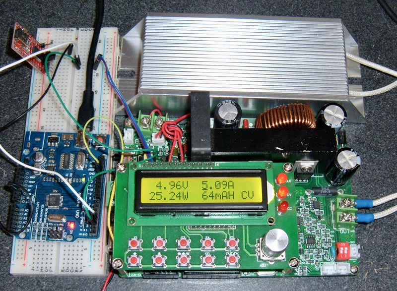

Last week, I reviewed a very nice MingHe DPS6015A buck converter - and I liked it. A lot! But I didn’t have time to cover the serial communication, other than to tease that I was going to cover it. And, this week delivers!
Documented, for the first time in English (that I know of), the full serial communication protocol for the MingHe DPS6015A (and related) buck converters! Plus, a bonus Arduino library to handle them in operation.

Why might you want this? There are many, many situations in which a programmable buck converter is a helpful thing to have - and, normally, they’re very expensive. This one is about $70 on eBay, is reasonably accurate (especially in voltage), and supports a multitude of serial interfaces.
Keep reading for all the juicy protocol details!
The DPS6015A
If you haven’t read last week’s review, you really should. I assume you’ve read that here, and are looking for more details on how to use this - and how to control it over serial.
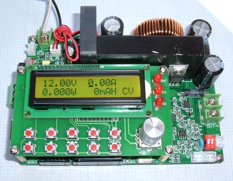
In a nutshell, it’s a buck converter that will convert up to 80V of input voltage to an output voltage between 0-60V, 0-15A, and up to 900W (at 60V/15A). And, based on my testing, it’s a pretty darn good one. The UI is good, the voltage accuracy is excellent, and the current accuracy, while leaving a bit to be desired, is still pretty good. And it has serial!
Serial IO Interfaces
One of the main reasons I like this buck converter so much is that it supports all three major types of serial interface - TTL, RS232, and RS485. If you want to control it with a simple serial interface, it will work - and, on top of that, the addresses are configurable, so if you want to hang a bunch of devices on a single RS485 chain (which is supported by that physical layer), you’re good!
TTL Signaling
TTL serial is a very simple serial signaling used by an awful lot of devices out there (including the Arduino, Raspberry Pi, and most other little hobbyist devices). It’s simple: 0V (or close to 0V) is a logic 0, Vcc (typically 3.3V or 5V, this board uses 5V) is a logic 1. Easy, but limited in cabling length - and you have to be sure the other devices can handle the logic 1 voltage.
Logical 1 on the DPS6015 is around 4V - which is admittedly a bit weird, but it exceeds 3.3V by a comfortable range, so I’ll call it a 5V device.
The standard Arduino Unos and Megas are 5V devices, so they can handle this. The Raspberry Pi is a 3.3V device, and the inputs are not 5V tolerant, so you’d need a logic converter to bolt this on a Raspberry Pi. They’re cheap on eBay, but you’ll need one. Or, at slow enough serial rates, you might get away with a resistor based voltage divider.

What’s the pinout for this port? Why, I’m glad you asked! It’s entirely undocumented anywhere in the manuals. Here you go!
G: Ground.
TX: Transmit (data from the device).
RX: Receive (data to the device).
5V: A 5V reference(ish) signal.

RS232 Signaling
RS232 is what many people think of as “serial” - it’s the 9 pin (or, on very old machines, 25 pin) serial interface that hangs out on the back of older computers. This uses a positive/negative voltage signaling over a fairly wide voltage range. Positive voltages are a logic 0, negative voltages are a logic 1 - but the voltages can range from +/-3V to +/-25V. The higher voltage swings make longer range links possible, but are not compatible with most “maker” equipment. On the other hand, if you’ve got an old industrial control PC, RS232 is great! The DPS6015A is properly configured as terminal equipment, so the normal cables used to talk to a modem or such should work fine.

RS485 Signaling
RS485 is the fanciest of the serial protocols supported - it has two signal wires and (normally) a ground reference wire, and it uses differential signaling (one line goes high, one line goes low to signal one value, and the inverse signals the other value). This helps make signals more robust against interference (common mode interference cancels out when the two signals are subtracted). RS485 is also designed for handling multiple stations on a serial link - it’s a point to multipoint link, which explains why these buck converters support different addresses. With RS485, you can have many of these run off a single link, and the units simply ignore commands that are not for them. The connection is to the left of the DB9 port for the RS232 serial, and there’s a jumper that allows you to enable or disable 120Ω termination of the bus. You have the standard A/B connectors and the G (ground or common) connection here.

Supported Baud Rates
Baud rates are simply “How fast the serial line toggling happens.” It’s not actually the (data) bitrate over the link, because serial links normally have start and stop bits, as well as (on some links) a parity bit to ensure somewhat reliable transmission (at least, detect a single bit flip in the message).
The DPS6015A supports the following baud rates: 1200, 2400, 4800, 9600, 19200, 38400, 57600, and 115200. So, standard PC baud rates up to 115200 baud, and nothing exotic or annoying to deal with. Excellent!
These are selected (if you don’t know what yours is set to) from the menu - with neither voltage or amperage limits selected, rotate the knob to “Set BaudRates,” press “OUT/OK”, use the knob to select the desired rate, and hit OUT/OK again to choose it.

If you find yourself working on serial links much, you’ll eventually discover that there are some weird crystal oscillators often attached to UARTs - things like 1.8432MHz. These happen to be easy to divide down to the standard baud rates with integer counters.
The default baud rate is 9600, and I can’t come up with any good reasons to change it. This is comfortably within the range of software serial interfaces on Arduino, and for sending a dozen or so characters back and forth, it works fine. It’s about a millisecond per character transmitted/received. If you need higher speed control, bump up the baud rate! The device doesn’t respond properly to very rapid read-after-write requests anyway (it needs a few ms to settle), so high speed links just spend more time waiting.
Also worth mentioning is that the serial interface uses the reasonably standard 8N1 serial encoding - 8 data bits, no parity bit, 1 stop bit. This is the default for pretty much everything unless you change it, so it shouldn’t cause any issues.
Device Addresses
Because RS485 supports multiple devices on a physical chain, the DPS6015A supports device addresses. The default is 01, with valid addresses being 01-99 inclusive. If you need to change or find the address, it’s in the menu options as well - scroll to “Set Address” and press OK, set your desired address, and press OK again. If you’re using a TTL or RS232 link, it still requires an address in the packets, but you should probably leave the address at 01. Yes, the UI has three digits of address, no, you can’t use all three.

LRC Calculation
With all that out of the way, it’s time to dive into the serial protocol on the wire!
The DPS6015A implements a basic Longitudinal Redundancy Check. The algorithm is pretty simple: For the entire command or response string minus the LRC character, sum the ASCII values of each character. Take the result modulo 26, and use this as an index into a zero-indexed set of uppercase characters to determine the LRC character (or get clever, which I do in my library).
So, for the string “:01rz6015”, the ASCII values (in decimal) are: 58, 48, 49, 114, 122, 54, 48, 49, 53. These sum to 595, which, modulo 26, leaves a remainder of 23. The 24th letter of the alphabet (remember, zero indexed array) is “X” - and that’s the string that comes from the device: “:01rz6015X” Every response from the device will have this, but you can set (in the menu options) if the device will enforce these on commands to the device.
Since command codes are only ever lowercase letters, and other values are numbers, the only place you should see an uppercase character is in the LRC code. If you see them elsewhere, something has gone badly wrong.
If you’re talking to the buck converter over serial by hand (why you’d do this instead of using the user interface is beyond me), you probably want these off - they’re a bit of a pain to calculate by hand. However, if you’ve got a software library talking to it, enabling LRC is a great idea to guard against communication errors causing a problem with the voltages/amperage setting - and my software library uses it. So turn it on.
Commands
Finally, the interesting (or dreadfully boring, if you don’t care about them) bit: How to send commands. These let you control just about everything on the unit, which is the whole point of this little gizmo!
Command/Response Format
All commands and responses share a common format: “:aaccxxxxL”. They start with a literal colon character, then two numeric digits for the device address, a two character (lowercase) command code, and then digits of data (if required - the read commands don’t include the digits on the command side). Finally, if LRC is enabled, the final character is an uppercase LRC check. Even if LRC is disabled, responses from the machine come with this character.
All commands and responses are newline terminated - “\n” in C, 0x0a as a hexadecimal value. You should not feed this device a CRLF, per the documentation.
However, it will respond with a full CRLF. Why? No clue. Just deal with it.
If you want to play with this device from your computer, I’ll make my standard suggestion for a cross platform serial console: The Arduino development environment.
Their serial monitor is simple to use, supports almost everything you might want (except weird microcontroller baud rates), and is easier to install than a lot of the sketchy serial stuff out there (for Windows). I’m lazy enough to use it on Linux and OS X as well.

Command List
After much buildup, we’re here - the list of commands you can send! This is broken up into two sections - “set” commands (which set values on the converter), and “read” commands (which read current status). I’ll describe what each one sets, but I assume if you’re this far in, you’ve read my review about how this unit works and are familiar with manual operation and power supplies in general.
A somewhat validly formed set command will respond with one of two values (and the proper checksum):
:01okJ
:01errQ
This does NOT mean the value was properly set - :01saqasdf\n gets a :01okJ response. But it does mean the command was received. You’ll only get the error response if you send something incomplete - :01\n, :01s\n, etc. The state machine is pretty stupid, so make sure it’s doing what you want! The software library I wrote should take care of it, but if you’re writing your own, just be aware that it’s about as stupid as can be.
Read Commands
The first set of commands is the “read” commands. These are, as one might expect, read-only commands that read some bit of state from the machine. They are sent with something like :01ru\n.
For read commands, you can chain them together if you want (after the initial r). Send additional characters and you’ll get additional responses! For instance, if you want to read the measured voltage, the measured current, the maximum set voltage, the maximum set current, the time, and the capacity, you could send :01rvjuita (newline terminated) and get back the following:
:01rv4200N
:01rj0142C
:01ru4200M
:01ri0500Z
:01rt0000000284V
:01ra0000000112S
Notice that each command comes back with a full response (colon, address, the full read command, and then the data). It’s handy if you want a bunch of data at once, but it’s not something I support in my interface code. You might want to use this if you’re doing tight data logging, though. It should be noticeably faster than sending each read command individually.
You cannot send more than 10 commands this way! The device will not handle it properly, and will spin in a loop on the 10th command (sending the 10th response) until you power cycle it! Don’t do that.
Read Voltage Limit: ru
The Read Voltage Limit command reports the currently set voltage limit (as a 4 digit value in 10mV units, so 3000 means 30.00V). Note that this is NOT reporting the actual voltage - this is the set limit that the unit won’t exceed. Example read: 42.00V.
:01ru
:01ru4200M
Read Current Limit: ri
Much the same as the Read Voltage Limit command, this reads the currently set current limit in units of 10mA. Example read: 5.00A.
:01ri
:01ri0500Z
Read Voltage: rv
The above commands read the limit for the voltage or current. The Read Voltage command reads the actual output voltage at the time of the read. There are a variety of reasons this could be lower than the set maximum (if you’re limiting on current, or if your set voltage is higher than the power supply voltage - this isn’t a boost unit). Example read: 42.00V (currently on the output pins).
:01rv
:01rv4200N
Read Current: rj
Like the above Read Voltage command, Read Current shows the actual current flowing through the converter at the time of the command. Example read: 1.42A (which may correlate very closely to what my office lighting happens to be drawing at the moment).
:01rj
:01rj0142C
Read Output State: ro
Read Output State will return a single 0 back if the output is off, or 1 if the output is on. In this example, the output is on.
:01ro
:01ro1N
Read Limiting Factor: rc
A power supply like this will either be limiting output to the set voltage, or to the set current. On the hardware, you can see which it’s limiting by based on the LEDs (and the LCD), but this is also exported in the Read Limiting Factor command. You get a single digit back. 0: Output off. 1: Voltage limited. 2: Current limited.
:01rc
:01rc1B
Read Watts: rw
The Read Watts command returns the current output power (volts * amps) in mW. This has a few more digits than most of the responses. Here, the output power is 59.64W (59640mW). Yes, I have 60W flowing into my lighting LED network (well, really into the buck converters that feed the 12V LED strips).
:01rw
:01rw0000059640I
Read Amp-Hours: ra
This reports amp-hours of output in mAh. Here, 1021mAh (1.021Ah). This does not reset if you turn output off and on, only if manually reset or if the machine is power cycled.
:01ra
:01ra0000001021S
Read Runtime: rt
Read the number of seconds output has been enabled. Here, 2450 seconds (a hair under 41 minutes). Like the Amp-Hours command, this does not count up if output is disabled, but it doesn’t reset to zero if you turn output off and back on either - it’s total output time since either the time was reset or the machine was power cycled.
:01rt
:01rt0000002450S
Read Temperature: rp
If you want to know how hot the converter is running, Read Temperature will tell you (in degrees Celsius). This is the temperature of the power conversion bits, not the ambient air, which is what the various protection temperatures respond to. Here, 39C.
:01rp
:01rp0039N
Read Protection Temperature: re
The protection temperature is the point at which the machine shuts down output to prevent further overheating. This defaults to 120C, but you might want to drop this down a bit if there’s no reason the machine should be getting that hot. Here, the example returns 120C.
:01re
:01re0120T
Read Fan Start Temperature: rf
If you’d like to know what temperature the fan starts at, this command will help you out! It reports the fan start temperature in Celsius (here 60C).
:01rf
:01rf0060X
Read Fast Voltage Change: rg
If you have no idea what this is, I touch on it in my review. If it’s enabled, like other binary configuration values, you get 1 back, and if it’s disabled, you get 0 back. If you have a normal load connected, this doesn’t matter. If you’re using this as a battery charger, you’d better have this disabled if you change the set voltage at all.
:01rg
:01rg1F
Read Boot Output State: rs
If you’ve set the machine to enable the output (from the M0 slot) on power-on, this will report 1. The default, in which output stays off on power-on, will return 0.
:01rs
:01rs1R
Read Beeper Status: rx
If you want to know if the beeper is enabled, this will tell you! Like previous binary commands, 1 means the beeper is enabled, 0 means it’s disabled.
:01rx
:01rx1W
Read Machine Model: rz
If you want to know the machine model, use the Read Machine Model command! The first two digits are the maximum output voltage supported, and the second two are the maximum output amps. In this case, my machine (the 6015) can output up to 60V and 15A.
:01rz
:01rz6015X
Read Communication Version: rr
This returns the machine communication protocol version. Apparently, mine is 22. I don’t know what other valid values are out there.
:01rr
:01rr0022H
Set Commands
The set commands are similar to the read commands, but they don’t respond with the new value - they simply respond (if you’ve sent a valid-ish command) with the :01okJ sequence. The device isn’t terribly tolerant of weirdness here, so if you send something outside the expected pattern, it will probably do something. That something may or may not resemble what you wanted. If you send it something weird and it fries your equipment, that’s on you, not me! I’ve documented the correct forms of the commands.
The x sequence after each command shows the number of digits expected for the command. In general, the unit seems to take fewer (or more) digits properly, but I’ve verified it with these digit counts, so you might want to stick with them.
Set Voltage Limit: su_xxxx_ (0000-6000, or your board’s maximum voltage)
Set the maximum voltage in units of 10mV (or volts * 100). This means 1000 sets 10V, 0258 sets 2.58V, etc. The maximum allowed voltage is determined by the model (60V on mine). If you set more than the maximum voltage your board supports, you’ll get an “ok” response, but it won’t actually set anything. Here, I set the limit to 41.00V.
:01su4100
Set Current Limit: si_xxxx_ (0000-1500, or your board’s maximum amperage)
This sets the maximum current (CV mode), or the current limit (CC mode). Like the voltage setting above, it takes 4 digits, corresponding to amps times 100 (or 10mA units). 1000 corresponds to 10.00A, 0250 corresponds to 2.50A, etc. Here, I set the amp limit to 5.00A.
:01si5000
Set Output State: so_x_ (0/1)
Turns the output on or off. Pretty straightforward. If you want to turn the output on, send 1. If you want to turn it off, send 0. Here, I make my office dark by turning off the output to that particular buck converter.
:01so0
Set Amp-Hours: sa_xxxxx _(0-65535)
If you want to reset the amp-hour counter, you can use this command to do it - set it to 0. If you want to set it to any other value, you can do that as well, though I’m not sure why this would be particularly useful. The amp-hour range this unit supports is a 16-bit unsigned integer - so 0-65535, or a maximum of 65.535Ah. Above that, it wraps back around to zero (and beyond). Be aware of this, or you’ll spend a long while trying to figure out what on earth is going on. If you try to set it to 100000mAh, you’ll find the display indicates 34.46Ah.
This will take variable string length values, but it’s easiest to simply use 5 digits for all communications (it makes the code a bit easier).
The most useful case here is setting it to zero, like this:
:01sa00000
Set Protection Temperature: se_xxx_ (050-150)
Heh. Heh heh heh. I wrote sex! Am I mentally 12 sometimes? Why, yes, I am! This will set the protection shutdown temperature, in degrees Celsius. Here, I set it to 100C. If you try to set it outside the range of 50-150C, it responds “ok” but does not change anything, and 150C is way, way too hot to be running this converter anyway.
:01se100
Set Fan Temperature: sf_xxx_ (020-120)
Similar to the protection temperature, this lets you set the fan start point (in the range of 20-120C). Around 50C is a good point to set it, if you have no particular reason to set it anywhere else.
:01se50
Set Time: st_xxxxxxxxxx_ (0-4294967295)
Set the output on time, in seconds. This is, again, most useful for clearing it, but you can set it to a higher value if you want. Unlike the amp-hour counter, which is a 16-bit field, this is a 32-bit field. You can set it anywhere up to the maximum allowed value, but it will wrap. Like other fields, you don’t have to put all the leading zeros in.
:01st0
Set Baud: sbx (0-7)
Set the baud rate. You can use values from 0-7, which correspond to baud rates of:
0: 9600
1: 19200
2: 38400
3: 57600
4: 115200
5: 1200
6: 2400
7: 4800
The change takes place immediately - so you’ll need to talk to it on the new baud rate as soon as you execute this command. This impacts all the interfaces - they share serial settings. I’m setting it to 9600 baud, which is very sane for this unit. I don’t support this in my library because it’s silly and adds a ton of complexity to support.
:01sb0
Set Address: sd_xx_ (01-99)
If you want to change the address of the machine (the prefix after the colon in command addressing), this lets you do that. Valid addresses are 01-99, so you can set any address in this range to any other address. Personally, I wouldn’t use this at all - I’d set the address manually on each machine, and then never send this command on the serial bus. There’s no reason to change it over serial, but you can if you want! Here, I’m moving address 01 to address 99.
:01sd99
Store to Memory: smxx (0-9)
Store the current voltage/amperage limits to memory slot 0-9. Memory slot 0 is loaded at power on. Here, storing to M1.
:01sm01
Load from Memory: snxx (0-9)
Load parameters from the specified memory slot. Say, M1!
:01sn01
Set Boot Power State: ssxx (0, 1)
Set the power state at reset. If this is set to 1, the output will be on when the machine powers on, if 0, the output will be off. In this example, I set it to be on when the machine powers on.
:01ss01
Set Buzzer Enabled: sx (0,1)
Note that the command here is “sx” - it’s not a single s with more digits. Enable or disable the buzzer. Here, I enable it.
:01sx01
Set Fast Voltage Change: sgx (0, 1)
Enable or disable the “fast voltage change” feature. I cover this more in my review, but if this is enabled, the buck converter will sink current from the load to bring the voltage down to the target. If disabled, it simply disables output if the voltage is higher than set. If you have a battery bank hooked up to the output, “disabled” is almost certainly the correct mode of operation - as I’m setting in this example.
:01sg0
The Arduino Library
Finally, I promised an Arduino library. You can find it here:
https://github.com/Syonyk/MingHeBuckConverter
I won’t promise it’s perfect. Use pins 2 and 3 for the serial interface if you’re using my example, and I’m pretty sure I assume you have a 1Ω resistor bolted to the output for some of the tests, but it works, it sets things, and it demonstrates how to interface with this particular device! Also, I mirror the original English manual, and the Chinese protocol description.
If it doesn’t work properly, please, file bugs.
Final Thoughts
This whole post is thanks to Google Translate. This particular buck converter is widely sold as a “serial/TTL” unit - and it obviously has the ports, but nobody selling it has bothered to link to anything that resembles the actual protocol. I got really irritated one afternoon with a buck converter that had serial ports that I couldn’t talk to, and ended up on the MingHe website (the link is probably fine…). Enough Google Translate surfing later, and I’d found the page of the device I was interested in, and a Chinese version of the communication protocol (mirrored in the GitHub repo)! I can’t read Chinese, but Google Translate was good enough to get me started, and once I figured out where I was going and how the protocol worked, I was able to figure the rest out.
The LRC took some time to figure out, but with enough working examples (literally anything coming back from the device), I got it worked out. The description makes sense - if you already know what you’re looking for.
But, with it all worked out? This is an awesome deal on an awesome device.
Comments
Comments are handled on my Discourse forum - you'll need to create an account there to post comments.If you've found this post useful, insightful, or informative, why not support me on Ko-fi? And if you'd like to be notified of new posts (I post every two weeks), you can follow my blog via email! Of course, if you like RSS, I support that too.


