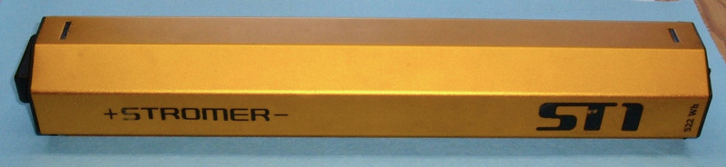

It’s been a while since I’ve done an ebike pack teardown, but this week, you’re in luck! I’ve got a 522Wh Stromer ST1 pack in my shop, ready to be taken apart! It’s a bright metallic orange, and it’s a beefy pack. There’s a lot of power in here, and the pack is quite dense in the hand.

What’s inside? What makes it tick?
You know you want to see another battery teardown, so jump on in!
The Stromer ST1
If you’re not familiar with Stromer, they’re an ebike manufacturer. They build a line of very nice, quite rugged ebikes, and I hear good things about them from the riders. The ST1 is their original offering, and the battery lives in the thick diagonal tube. It’s a bike that reminds me, in many ways, of my Seattle Commuter build (which is still in pieces after I sheared some bolts off in the frame).

One of their batteries has made it into my office - and, well, battery packs that come into my office rarely avoid being disassembled. This one is no exception, and I’ll go at it with my normal cold screwdrivers.
The ST1 Battery: 522Wh of 36V Fury!
The side of the battery case points out that this is an ST1 battery - and also, helpfully, points out the capacity - 522Wh. That’s a hefty battery - this battery will run an electric car for over a mile, or an electric bike for… oh, 15-30 miles, depending on how much assist you use, the terrain, speed, etc. It’s a good sized pack, comparable to the battery I used in my Seattle Commuter - and designed for similar things.

Looking at the end of the battery, we see the main power connector. Unlike most ebike batteries, this just has a single connector - no separate charge port. The charging is handled, somehow, through the bike. As I don’t have the bike, only the pack, I can’t offer much advice on how they work it out.
I can say that this is the same connector that BionX uses - a 7W2 connector. The two large end sockets are the positive and negative sockets (one with a bit of a spider web in it), with the middle pins being used for various other things (usually communication or a low voltage supply for a console, lights, etc). The tag mentions that this is a 36V/14.5Ah pack, which works out to 522Wh, exactly. I might be inclined to call it a 37V pack (most lithium cells have an average voltage over a useful range of 3.7V, and this is a 10S pack), so if anything, the rating is conservative. Not having the equipment to properly test the pack in fully assembled form, I’ll take them at their word. For per-cell capacity, 14.5Ah / 5 cells = 2900mAh per cell, which is a common enough size, and very reasonable. I have_ no_ complaints about what they call this pack, which is nice. I’ve been pulling apart tool batteries that are well and truly “creative” with what they call things. Marketing had no input into this pack’s spec tag!

Going Inside
If you look at the first photo, you’ll see some openings in the metal case. These are for tabs that secure the ends in - but if you expect the case to pop open easily, you’re in for a surprise. The ends are gooped in quite well. Pushing down fairly hard on the tabs with a standard screwdriver, then prying slightly (push the tab towards the end) works well, but the ends are really in there. Eventually, enough prying is rewarded with the end coming off. On the connection side, there’s some foam blocking, and, wonderfully, a bunch of removable connections! I love modular packs that come apart, even if nobody bothers selling parts for them… still makes my teardowns easier.

Here’s a better look at the compound holding the end in - it’s a thick, rubbery, black foam… wait, I’ve seen that before. Not as bad to get through, though.
I shouldn’t say all the connections are modular. There’s that pair of black wires going into the pack that doesn’t have a removable connection. It’s just soldered straight to the connector. But, those wires look very suspiciously like the normal wires for…

Yup! A temperature probe. The tape comes off, the probe pops out. Excellent. This is a standard 10k NTC thermistor, wired up to the external connector so that the external hardware can monitor the pack temperature (even if the BMS has shut down or is acting up). Usually, a charger checks this before starting charging - you don’t want to charge a pack that’s too hot, or that’s too cold. If you’re comfortable in a long sleeve t-shirt, the pack is probably fine to charge, but I don’t like to see lithium charging outside about 45F-90F. Above that is OK, just hard on the pack longevity-wise, and below that runs an increasing risk of lithium plating, which is permanent capacity loss. Let your packs charge at room temperature.

The other end of the pack has the same sort of tabbed connector - just push and pry, they pop out. More of that black foam, but unlike the Trek pack, this hasn’t made the pack difficult to disassemble (yet). It does offer some really good waterproofing, and while I wouldn’t go about scuba diving with this pack, I’m perfectly happy calling it “reasonably waterproof” - it won’t have any problems with year round weather, even somewhere soggy like Seattle.
You’ll notice a nice foam rubber pad here - the pack is very well shock proofed. A hard metal shell, and plentiful padding internally to help prevent shocks from making it to the cells.

Removing the Guts
With both ends removed, you can shove the core back and forth, but it doesn’t come out easily. The rubber compound around the end blocks it - both ways. Attempts to apply more force ran into the limits of what seemed like a sane amount of force to apply. So, I grabbed a sharp tipped flat blade screwdriver and started chiseling away the foam. It comes out easily enough. You can see here how the bead was applied before the end plates went on - the material is squared away where it touched the end plate.

With some of the foam removed from the ends, the whole inside of the pack slides out. It’s in there firmly, but not excessively tightly - the friction getting it out is from the foam at the ends. Again, you can see some foam padding along the sides that helps keep the pack protected from shocks. It’s a long battery!

Inside, there’s a label. HiTech… this rings some bells. Going back a long, long way, this is the same name that the iZip Ultra BMS had. Same company? No idea, but likely. There can’t be that many “HiTech” companies in the ebike industry. Again, same ratings as on the outside - no creative marketing here!

Finding the way in further took some looking - the seam of the black wrap is almost entirely hidden under one of the foam buffer strips. Many layers of protection inside this pack - I like it!

With the wrapper removed, we can see the cells - Samsung INR18650-29Es. A good cell, by a good cell maker. Nothing dramatic here, just a well chosen cell. They’re rated for 2.75A continuous (so 13.5A for the pack, or a hair under 500W), and 8.25A peak (41.25A, or about 1500W). Plenty of current capacity, and while they’re nominally 2850mAh, you can get them up to 2900mAh at low discharge rates.

Skipping forward slightly, the pack is an “out-and-back” arrangement - negative at one side of the BMS end, extending down to the far end, bridging the center, and coming back. You can see the layout from the end, and there’s a heavy plastic protector in the middle. This serves as some structural strength, but also to prevent the cells on opposite sides from shorting together. It’s a lot of plastic thickness.

For the cells running down each row, they’re positive to negative, bound together with custom cut nickel strip. You can see how the pack is “folded” on the inside and outside edge here - if you look at the left joint, you see two ends of nickel strip (which, if touching, just helps improve conductivity). On the right joint, you can see the pair of folds on the outside. The pack is built in a “long” configuration, and then is folded into the cases and taped. I’ve not seen something quite like this, but I like it - there’s no way for rubbing through insulation to cause a short circuit, because every folded bit of nickel is at the same voltage across the whole thing.
Because the pack is still in decent shape, cell-wise, I didn’t pull things apart further. From the end plate and how things are folded, the layout is obvious, and I’d rather not pull apart a hunk of cells that’s a useful arrangement for me. I may bolt my own BMS on it at some point, but I have an awful lot of 10S packs laying around my office, and this is yet another one I can make use of!

BMS-End Connections
Going back to the assembled pack, the BMS end has the usual assortment of connections for a modern pack. There’s a many-colored wire connector bringing out the cell group voltages for balancing and low/high voltage cutoff (a good BMS will turn off charging/output if any cell group exceeds the limits), and the output connectors with some nice screw terminals.

Flipping it over, the other side of the pack contains some paper towel fuzz from my workbench, and the screw connectors that connect the main pack ends to the BMS for output control. You’ll notice that all the high power screw connections are “gooped” with some sort of rubber sealant. This prevents them from backing out in a high vibration environment - say, an electric bike getting ridden on gravel! I really like the screw connections here. I haven’ had to pull out a soldering iron yet, and it looks like I won’t have to unless I want to swap out the balance wires! Everything I’ve seen so far indicates that people who knew what they were doing were left alone to build a really nice, reliable, long-lived pack. It’s not a cheap Chinese Special, but I’ve also not seen anything that seemed purely overkill to me - it’s well thought out for the environment, well assembled… no complaints yet!

The end of the BMS contains four promising looking screws. Let’s unscrew the main power leads, remove the balance plug, remove the screws, and see what happens!

The BMS
With a little bit of fiddling, and removing a few more temperature sensors, the whole BMS comes free! This is a double layer BMS (first one of those I’ve seen on an electric bike), though the total board area is comparable to other units I’ve seen. The big hunk of metal on top is a heat sink for the switching FETs, and the battery/pack connectors are these massive bits of metal, firmly soldered into very large planes on the circuit board. Beefy! The fuses aren’t replaceable (easily) - they’re soldered in. From a longevity perspective, that’s perfectly reasonable, and it means you won’t have a loose connection at that point in the future.
The whole BMS is sprayed in a conformal coating, which I like - but it’s not consistent across all four layers. This is the first real complaint I have - they should properly cover the whole BMS, not just the ends.

What does the board say? ST1005A-PWR Rev 1.5F, 2PUM03140P02. The bar code on the heat sink is almost identical, but with a Q instead of a P - 2QUM01200P02 V0.4. What’s it all mean? No idea!
Unfortunately, I can’t read the transistor IDs through the coating.

The two layers come apart with some screws. The BMS is logically separated into two different boards with the upper board handling the high power handling, and the lower board being the logic board (and balancing electronics). This is a really good way to design a BMS - the high are kept in their own space and don’t have an easy way to interfere with the logic side.
The bottom of the board contains a fairly large filter capacitor, the usual anti-reverse-charging diodes, and some hardware for controlling the switching transistors. On the right, you can see the interface between the two boards - and it’s labeled! Woo!

I’m so happy to see things like this on a BMS. Labels are good. You can see some inconsistent conformal coating here - I think it was applied to the BMS after the two layers were assembled, which is nice, but it would be better if they’d covered everything.

The lower board contains the logic guts, and also handles the balancing. Balancing currents are far lower, so there’s no problem putting them in with the logic components, and you need quite a few more traces to control the bleed resistors anyway.
The square IC on the left is an OZ890TN. This is a full featured battery management chip that handles all of the battery interface features - balancing, voltage limits, current limits, etc. You can see that it’s about half coated, and half bare.
To the right, the rectangular IC is a PIC18F25K22 - a little microcontroller that interfaces with the BMS chip and handles the rest of the pack functions. This chip is going to handle communication with the rest of the bike for showing back capacity remaining, and it may interface with the charger - I don’t actually have a Stromer, so I’m not totally sure about the details.

UART wires! This probably means that the BMS talks to the rest of the bike over serial. I’m not sure why you need four wires, but… this would be a good place to go poking, if you had a Stromer, and wanted to understand the protocols involved.

Flipping the board over, you can see a row of transistors and bleed resistors for balancing the pack. There are 10 little transistors to switch the segments on and off, and… 7 resistors. I’m not quite sure how this is wired up, actually, but it seems to work fine for them. There are some extra unpopulated spots that would likely be used for a higher voltage pack, if they ever add one of those. It’s not fully wired for that, but at least some of the routing is done already.

Final Thoughts
I’ve seen some sketchy packs, I’ve seen some good packs. This pack? This is a good pack. It’s well thought out, well put together, has a competent BMS split nicely between the logic and power sections, and it’s very well protected. Nobody is going to shake this pack apart and damage it without tossing a bike off a cliff - and even then, the pack would probably be just fine. If anything, it’s a bit over built - which impacts weight and cost, but I’m not going to complain too much.
Is it rebuildable? Yes, it should be, assuming the BMS doesn’t do anything particularly stupid. I have no idea what protocol it speaks, or what the command structure is, but I expect the pack is rebuildable without heroics.
Will I rebuild it? Surprisingly enough, no. You can find other people who will, and I’d suggest hunting them down. It’s a somewhat complex pack to rebuild, ideally done with custom cut nickel plate. I’m trying to move on from doing quite as many pack rebuilds to some more interesting projects that require more time and effort. Plus, with the new kid, I’m trying to spend more time with the family, instead of out in my office spot welding. Priorities and all. So, find someone else to do the rebuild.
I’d been hoping to kick start the electric bike battery rebuilding process with my blog and rebuild services, and it seems I’ve done that. So, I’m not going to add this pack to the list of things I’ll mess with.
Also, I bought a used Chevy Volt this week.
Comments
Comments are handled on my Discourse forum - you'll need to create an account there to post comments.If you've found this post useful, insightful, or informative, why not support me on Ko-fi? And if you'd like to be notified of new posts (I post every two weeks), you can follow my blog via email! Of course, if you like RSS, I support that too.

