
Or, “Things that didn’t work.” I’ve been working for a while to build some really, really nice audio cables that meet spec as DMX cables as well. Why? Personal challenge, and to replace some of the older audio cables my church uses. I’ve gone through and “tourized” a bunch of XLR cables to make them more rugged, but for not that much more than a pre-built cable, if you’ve got a soldering iron, you can build yourself something properly nice - with, at least on paper, far better audio performance in the bargain!

This road has not been smooth. I like to document my failures as well as my successes, both because they’re interesting, and because, hopefully, someone can learn something from them and avoid going down the same false paths I have. If you want to watch a video of a beautiful build process, go watch The Art of Making a Nixie Tube. If you want to find out how not to build some high performance XLR cables, stick around here!
You… huh? Audio cables are audio cables!
Are they?
Well, yeah, for most purposes, they are. You probably can’t hear the difference between a fancy cable and a low end cable in the audience, and that’s fine. But, you’ll certainly notice the popping and clicking and snapping from a bad connector getting flexed. Or you’ll hear the blown speaker from coils trying to follow those transients. As I’ve learned, weekly setup and teardown can be really rough on cables, especially when there are a lot of people (and plenty of kids) helping. I’m all for kids helping, but the reality is that a three year old isn’t always the easiest on a cable. Running across the room dragging it behind, to shove it in a box… well, it’s not great for longevity.
I set out to build a really high quality cable - both physically and electrically. Physically, I want a cable that can handle all sorts of abuse and is generally resistant to connector end failures. But, at the same time, most DMX controlled lighting equipment uses three pin XLR connectors now, which means the same cables are going to get used for lighting and sound. Audio cable “usually works” for carrying DMX, but if I build a cable that meets DMX spec, I’ll have a properly good audio cable as a result!
Don’t worry - I’m not going down the audiophile rabbit holes of “sound stage” and “imaging” and “sparkle” and other vague terms that mostly translate to “I’ve convinced myself that this $1000 cable sounds better than a pair of shoelaces soaked in salt water.” I’m going to stick to things I can measure - like capacitance between conductors, and, to an extent, raw physical strength.
But, to start off, let’s look at the difference between some cheap cable and some nice cable.
Belden 7200A vs “Audio Cable”
Belden makes some very nice cable. They make a very nice flexible DMX cable. It’s the 7200A - and it’s green. Blindingly, brilliantly green. I have a bunch of it. I also have some cheap cable. Let’s compare and contrast, shall we?
The difference is obvious when you start handling them, before you even dig in. The Belden cable is somewhat thicker, and simply feels like a better cable. It’s smoother to bend, has a somewhat slicker outside surface, and, while being a super minor thing, has the outer labeling printed with an ink jet printer (you can see the “dot matrix” style printing) versus a wheel printer. Which looks nicer? The wheel printer. Which is another way of putting possibly inconsistent pressure on a cable? The wheel printer. Belden doesn’t make low end cable. They’ve patented more than a few things related to making seriously consistent cable, and they care a lot about the quality. Does it all matter? Probably not for most people, but if you’re going to build high end cables, you may as well start with the best!

Most modern signal cable has some sort of shield around it. This shield helps to keep external interference out, and helps keep the cable from creating interference to mess with other things. Reasonably obviously, this shield should go all the way around the inner signal pairs. It doesn’t help much if it’s lumped off to one side leaving huge gaps (though depending on the frequencies involved, that may not be particularly awful either).
Strip a bit off the ends, and… ah, yeah, the cheap cable has some copper shield wire, but it’s not at all consistent. It’s just basic strands, and that huge chunk of white string exposed? That’s an unshielded section. Even if the copper shield starts out consistent, it’s prone to move around as the cables are bent, flexed, twisted, and generally used.
The Belden cable, on the other hand, has a woven shield that ensures the covering is not going to slide off to one side (either during production or after extensive use - I don’t know if the other cable’s shield slid off during production or during use, but it’s not properly shielding now).

The shield wire goes to pin 1 on the XLR connector, so we’ll just twist the shield off to one side. On the cheap cable, that clears it entirely. On the Belden cable? The shield is just the outer shield - there’s a metal foil layer inside that, fully covering the internal wires. Which of these do you think is more likely to reject interference? Foil insulation gives good coverage, but tends to be somewhat high resistance. Having it in contact with a woven wire shield allows the foil to rapidly dump any current out to the wires, which carry it to a ground somewhere. The two pair together very well.

With the shield cut away, I’ve bent the signal conductors off to the left, and left the support wires (or threads) in the center. The Belden cable uses some soft plastic structural conductors to improve flexibility, provide physical strength, and help position the other cables properly (they’re twisted to help reduce interference yet more). The cheap cable? It’s some soft twine. It works, but it’s not nearly as nice, and it doesn’t provide nearly the same positioning strength as the soft plastic.
There’s another difference that isn’t terribly obvious in photos. The insulation on the wires in the Belden cable are foam polyethylene, and the insulation on the cheap cables are almost certainly PVC. They both insulate, in terms of keeping electricity from arcing around, but they have radically difference capacitance values. Foam PE is far, far lower capacitance than PVC or the other cheap insulations, and we’ll see this in some of the cable build results. For audio cables, this does make a difference in how the cable passes high frequency audio, and it makes a big difference at the high frequencies a DMX cable has to pass. Even though DMX only signals at 250kHz, to get a reasonably square wave through at that frequency requires the cable pass frequencies well north of 1MHz, and capacitance starts mattering there.

With the outer insulation removed, you can see everything that makes up the 7200A’s guts spread out. It’s a very nice cable to work with!
Do you really need such a high end cable? Probably not. But, again, if you’re going to build yourself some nice cables, you might as well start out with a good cable. This is flex rated to a million cycles, has great capacitance values compared to cheap audio cable, and is just a joy to work with compared to the cheap cables. I won’t claim it will make any measurable impact on your sound, but you can measure the difference between the cheap cables and this stuff, and it’s quite strong in the bargain. No cheap rubber jackets here!

The Goal and the Design
My goal? High strength cables that will tolerate massive amounts of physical abuse, for years, without having a connection fail - while being valid DMX cables as well.
The design? Use high quality starting cable, like the 7200A I have. The only problem is that this cable is very, very green - which won’t look good on stage. Fortunately, you can get good looking nylon cable loom that makes the cables mostly black, while still letting through enough of the underlying color to make them look interesting. High end audio cable tends to have this sort of sleeving, and it provides additional protection for the cables, as well as adding physical strength in tension, which is what I’m concerned about. The sleeves also tend to be somewhat torsionally stiff, so you can’t “extension cord wind” a cable - they simply don’t twist enough to get away with it. You shouldn’t be putting that kind of a twist in a cable anyway, but too many people do.

My plan was simple enough. Cover the wire in the loom, use some heavy duty adhesive heat shrink to secure the ends in place, put the XLR/DMX connectors on, and go! The reality was somewhat more complicated, as it often tends to be. This week is the lessons learned, next week is how to actually make something decent!
Lesson 0: Sizing is hard!
Never having worked with wire loom of this variety before, and not having a great feel for what size heat shrink tubing I’d need, let’s just say I have a lot of samples of various diameter loom and various diameter heat shrink in my office now.
Since I made some handwaves and assumed it would work, this added a lot of delay to the project as I had to wait for new parts to arrive.
What are the correct sizes? You’ll just have to wait until next week, when I actually give a parts list for something that works well! But I pretty much Goldilocksed it - the first loom was too small, the second loom was too big, and the third was just right. Sequential shipping on that took about… oh, 2 weeks.
Experiment 1: Adhesive Heat Shrink
My first mostly-failed experiment was the original plan: Use a nice, thick, adhesive lined heat shrink, wrap it around the end of the nylon sleeve, and put the connector on. It sounded like a good idea, and it looked really good - it just didn’t actually work as intended.
I bought a new soldering station earlier this year. It’s got a pump in it that gets used for solder fume extraction, and there’s also a hot air rework wand. Or, in another configuration, just about the ultimate heat shrink tool. You can set the temperature and airflow such that it will shrink heat shrink very well without scorching, melting, or burning anything else around. Totally awesome - and, with the heat shrink applied, looking pretty darn good. (“Who shrinks heat shrink? Frink shrinks heat shrink!”) I went with adhesive lined heat shrink to help keep everything in place. Non-adhesive heat shrink is thinner, but it’s easier to pull things apart. Since these are rough duty cables, stronger is better. The goal is that the adhesive bond firmly to all the layers, and soak through the weave to secure everything to the jacket.

Strip the end back, pull out the wires, tin them nicely… all looking good so far. With the foamed PE insulation, be very careful with heat - the insulation melts back very easily. I use 250C for this work, and I could probably go cooler. I also didn’t use the full braid for the shield line out - it would be too thick for the solder cup. I used about half, which works right, and I flowed a lot of solder into it to help keep it together.

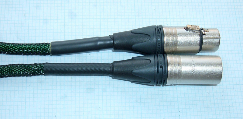
The problem came when I tried to slide the back half of the connection over the wire. It just won’t fit over the nylon weave and heat shrink. The rear end of the cone is rubber, but there’s a hard plastic ring that serves to clamp the “gripper” in place. That isn’t large enough for the full buildup diameter, so I don’t have much room to work. This was all I had to work with, which is sufficient to get the connection soldered. Unfortunately, it’s not enough to get the gripper in past the end. I even tried cutting the gripper apart, and I was able to get one section in, but not the rest.
Without the gripper, the connection doesn’t have a great physical link to the wire, and that means this approach won’t work. It’s valid for a quick test connection, but for production? No way. So, you can’t use the stock Neutrik ends with this thick cable and more stuff on top.

Experiment 2: Non-adhesive heat shrink
With the adhesive heat shrink being too large around, I decided to try some non-adhesive heat shrink I have to see if it would be thin enough for everything to work. Because it doesn’t have the goop, I used a longer strip and put it back over the nylon in an attempt to get everything to grip.

Result? I could get the back cap over the heat shrink - which solves one problem I had. But, the grip on the heat shrink and nylon just isn’t very good. Even baking the heat shrink extensively, I couldn’t get it tight enough that it gripped properly. The cable could still slide in the heat shrink and nylon with enough force, which is no good. Being able to slide things relative to one another means that the inner cable can pull back separate from the nylon and heat shrink, which can stress the connections. And that’s exactly what I’m trying to avoid.

In any case, I continued the build to learn what I could. Connections tinned again, same as the last time, though you can see a tiny bit of flaring at the end of the insulation from it getting hot.

For assembling the pin side of a connection, I like to use another random XLR connector to hold the pins in place. This prevents them from moving when the plastic is soft (which happens, at least on cheaper connections, while soldering). Plus, it gives you a nice hand grip that won’t burn you. I’ve burned more than one pin mark in fingers picking up a male XLR end before it had fully cooled. The only downside to using a gripper like this is that it’s a heat sink as well. You might try leaving the end only barely in to prevent it from taking forever to heat.

I’m still working on the details of soldering this stuff. I think a bit more temperature on the iron would lead to a better result - fill the solder cup completely, then shove the wire in. I’m used to cheaper connections that don’t really have a “cup” - you’ll just run solder down the inside of the whole connection.

With the connections done, I put the gripper around the connection and proceeded to pot the insides with hot glue. You can see what’s going to be a problem, though. The gripper is splayed out at the gripping end - it’s really, really wide. Getting the back of the connection over is a problem.

I was able to get the back more or less closed, but I had to trim a bunch of the end of the gripper, and it was still really, really, unreasonably difficult to get it closed. It’s not even fully closed - you can see a bit of gap that shouldn’t be there.
Trimming the gripper down defeats the purpose, though it’s better than having to leave it out entirely. Back to the drawing board…

Two Failed Experiments - But One Usable Cable
Despite two failed attempts to put ends on (for my definitions of success), I did manage to get both of them connected, and the cable works fine. I might not subject it to insane amounts of abuse, but it works, and has been in service a few weeks. I’ll redo the ends with the newer method if they start acting up. They’re still quite robust compared to the cheaper cables.
Despite that, the sound guy is a huge, huge fan of it already! Even with the weak ends (by my standards), it’s a good audio cable, and it’s significantly stiffer than our other cables. Not unreasonably so, but it doesn’t tangle as easily as the really flexible cables when in our audio cabinet, and the nylon loom slides easily, so unrolling it is easier. Plus, capacitance is a good bit lower than some other cables!
So, What Works?
Ah. Yes. I have developed a parts list and technique that works to make amazing cables. You’ll want to check back next week for that! It turns out there’s a really easy fix to the problems.
Comments
Comments are handled on my Discourse forum - you'll need to create an account there to post comments.If you've found this post useful, insightful, or informative, why not support me on Ko-fi? And if you'd like to be notified of new posts (I post every two weeks), you can follow my blog via email! Of course, if you like RSS, I support that too.


