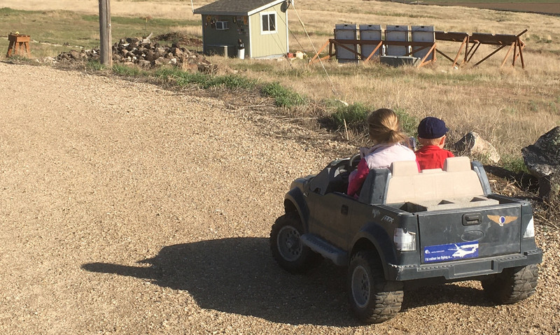

I’ve… got a problem with electric trucks. My kid’s PowerWheels F150 is now far more expensive than most of the vehicles I’ve owned in my life, if you consider the various upgrades it has.
It’s also a halfway competent little electric property truck, with a real throttle and brake pedal, and she’s learning to drive something that drives like a real car now.

This most recent upgrade is the East Coast PowerUp DIY ESC Kit - which is basically a total conversion kit for the chassis and motors. The only electronics retained are the motors, and the whole setup becomes far, far nicer in the deal. Not that it really impacts how my daughter drives - pedal to the metal, though we’re working on it!
What’s in the kit? How does it go together? Why would one do such an insane thing? Keep reading to find out!
Power Wheels: Stock Wiring
If you’ve ever played around with a “big” Power Wheels or similar kid’s car, they’re really quite simple. There’s a throttle switch (on or off) and a shifter that lets you select reverse (slow), forward slow, and forward fast. That’s it! A cute little lead acid battery under the hood gives you a bit of time to drive around, and sags badly enough under load to do a good job of cushioning acceleration.
The “core” of the system (it’s not really electronics, just some switches) is the transmission shifter. This is a set of two DPDT switches that are toggled by moving the shifter lever. They control the motor wiring (series or parallel) and the direction of travel - and that’s it. Forward slow is the motors in series, forward fast is the motors in parallel, and reverse is the motors in series with the polarity swapped.
On the floor, you’ve got the throttle switch, which does one of two things: Provide battery power to the motors, or short the motor windings for maximum braking. It’s safe enough, and doesn’t tend to fail in weird ways, but it’s somewhat violent - there is no concept of coasting. Without weight in the back, wheel slip means you just spin/slide the wheels for acceleration/deceleration - but it also means that you can’t get up a small gravel driveway slope, because there’s no traction. With a cinderblock in the back, it’ll hook up - and slam you around pretty hard.
The acceleration isn’t too bad with the stock little battery, because the voltage sags badly if you try to ask for a lot of current out of it. But if you were to, say, replace it with a stiff lithium pack? The motors, stalled, pull north of 50A (!) and it’s hard on the gearboxes.
So, one might consider replacing the stock control switches with something far fancier, and that’s exactly what I’ve done!
Is This Insane? Yes.
There’s no good justification for this sort of project. It’s entirely a “Because I can!” project that takes a perfectly functional kid’s electric truck, makes it mildly nicer, more complex to drive, more real-car-like, and involves spending more money than I’ve spent on quite a few full sized cars over the years (I specialized in “sub-beaters” for most of a decade, considering $100 cars a nice win). Between this kit and the large lithium pack I built for her truck, it’s far from the cheap $20 find I got it for - and I don’t care. It’s fun, she likes it, and she’s learning that you can fix, improve, and upgrade things to make something rough around the edges an awful lot nicer. By the time she outgrows it, her brother will be able to drive it, and if it survives him (which is actually an open question at this point), I’ll probably sell it to someone else.
The kit estimates 4-6 hours of time to get it installed, and that’s actually accurate. There’s a lot of little bits and pieces to cut, crimp, and assemble. If you enjoy this sort of thing, it’s relaxing enough. If the thought of a spool of wire and a bunch of crimp ends terrifies you, this isn’t a project for you. Maybe pay for the pre-built option, but that’s twice the cost and still requires a bit of wiring.
Seriously, though. Both of these cars (a Daihatsu Charade and a Subaru DL wagon) cost less than this kit, and they were whole, more-or-less running cars! Sure, they needed work, but what cheap car doesn’t?

I maaay have driven this Subaru for a couple weeks without a working clutch pedal - start in 1st and rev match. And I’m kind of surprised the engine tolerated how low on oil it was after a run up the highway with a leaking o-ring on the way to the cam tower. But it was a beast.

First: A Ferret!
I promised my daughter I’d use this ferret picture in the post, so, here’s a ferret. Frodo the Ferret. Snoofing around, looking ferrety, and generally being a weasel.

The ESC Kit
We’re talking about the East Coast Powerup 12/18/24V Universal Variable Speed ESC Kit ESC Kit - about $150 depending on options. I went with the normal options because I’m doing some of my own custom stuff already, and didn’t end up using quite all the parts (like the circuit breaker - my battery has a perfectly good BMS that will cut power above a certain current already).
If you order the normal, DIY ESC kit, you’ll get a pile of parts in the mail, very nicely stuffed into a box. I’m not nearly so good at putting them back in as they came - it’s a nicely packed bit of project. There’s a lot of wire, a lot of connections, and some pretty fun parts. Let’s dive in!

The most obvious new parts are the pedals. On the left, there’s a rather nice variable throttle. I expect it’s a hall effect throttle, but as it plugs into the controller directly, I didn’t test it. This is, after all, my daughter’s birthday present, and I’d rather not fry something before it works. Once she’s used to it, if she wants to analyze it, great. She’s already worked out that I take everything apart anyway…
The brake pedal on the right seems to be a nice SPDT switch - it connects the input to one of the two outputs, but not both. This pedal works as a nice safety switch on the system as well - pressing it will cut power to the motor, even if you’ve got the throttle held down.

Moving on, the core of the new unit is the ESC - Electronic Speed Controller. Everything else is based around this, and exists to route power from the battery, to this controller, to the brushed motors in the right direction. It’s got a couple power wires off it, a throttle cable, some smaller wires, but… what’s inside?

I’ll tell you! Two rows of power transistors, heatsunk to the case! This is quite nice to see - it looks like a halfway sane design on the inside. I’m not pulling it all the way open, simply because I don’t want to bother re-aligning everything, and, again, it’s my daughter’s controller, not mine to rip apart. There’s good heatsinking on both rows of transistors, and if they fail at some point, they should be easy to replace. I even see what look like spots for more!

From another angle, we can see it’s a Sayoon unit - that’s fine. I’d really like to pull it more apart, but it’s more important to have a working unit at the end. No major complaints from what I can see in this unit, and the caps at the far end, at least, are 63V rated. So, I’m sure it’s fine for a 24V system, and if you put more than that into a PowerWheels, you’re just twisting up gearboxes for no real gains.

Continuing into the box, there’s a bunch of relays stuck together - and this is actually the most impressive part of the kit, IMO. The kit is for a kid’s toy - and the relays are full on educational units! You can see exactly how they’re set up through the sides, watch them activate if you toss some voltage into the coils, etc. These are the core of the kit - they handle controlling power direction and braking, as well as switching main power to the system. The left two relays are the motor control ones, the right relay is the power relay. Almost every single connection is used!

Moving on, we have a terminal strip to connect everything, and a pair of voltage regulators that… regulate down to something. I’m not sure what’s in there, but it looks for all the world like two different regulators back to back. It’s oddly familiar - similar to one of my old DC-DC converter projects for ebikes!

The rest of the box is mostly a mess of wires and connectors. There’s a lot in here - which is part of why I like this kit! It really does include everything you need! On top is a circuit breaker I won’t be using (as I’ve got the battery BMS) and a charge port in the top right that just doesn’t match my setup right now.
There are TWO lengths of “thick black wire” in the kit. One is a fine stranded welding wire that’s quite flexible, one is a thicker “normal” stranded wire that matches the thicker red wire. The thick stranded wire is for the battery cable, the fine stranded stuff is for all the little relay interconnects. The finer strands bend better, though be careful stripping the insulation. It’s 12 gauge, but using a 10 gauge opening on the strippers will work a lot better and damage far fewer strands.

Finally, there are a ton of connectors and gizmos and gadgets! We’ve got, in no particular order, a ton of crimp connectors, a backup beeper, a big resistor for the brakes, an on-off switch, a precharge resistor that helps prevent arcing, and some terminal block connectors. I’ll be using most of these!

Starting the Install: The Prep Work!
If you’re inclined to start with taking the Power Wheels apart, think again. You’ve got several hours of work before anything that even touches the actual vehicle. The estimated install time for this kit is 4-6 hours, and that’s actually about right. You could do it faster, but the wiring diagram is “adequate” at best, and there’s a lot of “Well, you figure it out!” sort of steps in the install. They’re not missing anything critical, but you really do have to figure out a lot of it as you go.
My advice? Just start putting ends on things that need ends, because there’s a lot of this to go around.
One thing not mentioned in the directions - you’ve got purple crimp connectors and blue crimp connectors - plus some male versions of those. Pull the male ones out - it’s indicated where you use them. The purple ones are for smaller wire sizes, so anything that’s just a single small wire? Use the purple. The blue ones are better for the junction connections that require a few wires sticking out once, though on the ones that are just a small wire and diode, you might consider a purple one. It’s a bit hard to crunch the blues down enough for that.

Do you have a good set of crimpers? Not just pliers you’re abusing into being crimpers? If not, you’ll want to pick up a set. Your local home improvement store should have some, or you can order them online - but you really don’t want to just wing it with this kit. Troubleshooting loose connections later will drive you up the wall in short order, and once everything is crammed in, troubleshooting will be a pain. Do it right so you do it once.
I’ll suggest a “double crimp” with these - crimp one side tab over, then crush the other one down on it. It seems to make a really good connection. While you’re at it, yank pretty hard on the wire after you’ve crimped it. If it’s a good connection, it won’t come out. If it does come out, well, you made a crap connection that would have failed eventually, so redo it better.

Just start terminating wires from stuff. You need to terminate the brake pedal, the voltage regulator, the fuse (with a ring terminal), the backup buzzer, etc. Where multiple devices go into a single point on the bus bar, you can usually just have multiple spade connectors and stack them - no need to have them going into the same connector. There should be plenty of connectors, and having them separate makes assembly easier.

Sometimes, you’ll have to puzzle out wire lengths. For the power switch, for instance, you should have a roughly-similar length green and orange wire. Cut a length of the (rather long, because it’s used all over) thin black wire to match! Presto, a matching wire harness! Though for the switch, you might consider holding off on actually wiring it up until you’ve got a hole worked out for it. It’s far easier to put through the hole and then put the connections on.

While you’re on the bench, play around with how the connectors feel if they’re set properly, with the metal tongue properly seated between the teeth of the connector. It’s quite possible to get them set wrong, with the tongue between the connector and the plastic housing. This isn’t a good connection, and for the high current connections, will quite rapidly melt the housing and, if you’re lucky, just stink and cause things to stop working.
After you’ve finished with the easy stuff, start building the relay harnesses. Just follow the wiring diagram, and make sure the diodes are pointing the right way!

Just keep building. It goes together slowly, but does go together. You’ll be making a lot of these little black jumper connections, so keep the wire length down to what’s required. These are where you use the welding cable with the thin strands and flexible insulation. Seriously, just keep following the diagram. It’s all there, even if it’s a weird diagram.

Starting the Install
Once most of your pieces are together in the shop, take apart the car. Take it all the way apart. You need to rip out the stock wiring harness, the stock throttle switch, everything. The only stock wiring left is off the motors - cut this right at the connector to the transmission so you’ve got plenty of wire. Once you cut, you’re committed! Onward and forward!

I couldn’t resist using a cinderblock to hold up the disassembled pickup chassis… from this angle, suitably disassembled, it actually doesn’t look like a pickup at all. Or even really a vehicle.
While you’re in here, clean it out. We mostly disassembled the truck when we got it for cleaning, but never got around to taking the bed off. Knock out the dust, dirt, grit, spider webs, etc. It’s far easier to disassemble than a real car!

You’ll need to do a bit of body work on the car to fit the new throttle - it’s almost, but not quite, the same size as the stock pedal. It doesn’t quite fit. But it’s easy enough to do. For ours, at least, this is what the pedal opening looks like. You can either trim some down from the top or the bottom to fit the new pedal.

Based on positioning, I figured the top would be better. It’s a bit hard to see what exactly I did here with the shadows, but I’ve cut out the top rear plastic. I used a large drill bit, a battery powered drill on high speed, and basically used it like a router. Drill a hole, then use high speed and move the bit around to cut out the plastic. You make a mess, but it works quite well on this sort of plastic!

To fit the pedal to the outline of the floor, bend the end tab. As the instructions suggest, channel locks work well here. It fits surprisingly well. You can install it either way - with the hinge on top or on the bottom. For no other reason than “It seems right to me,” I put the hinge at the bottom. I’ve driven cars both ways, and I couldn’t tell you which I’m driving at any given moment, so I’m pretty certain it doesn’t actually matter.

My advice? Fit everything and route the wiring before you screw stuff down. I had to remove the throttle once or twice to route everything properly. You can see the hole I extended up towards the “firewall” to route the brake wiring. Initially, I’d run it under the edge of the metal plate, but consideration of the violence of banging around a gravel driveway and the possibility of having to redo wiring after it got cut… it’s worth making sure nothing is pinched on a project like this.
Screw everything down. Even though this spacing looks really tight, it seems to work fine for kid-feet! It’s not any worse than some Italian sports cars, from what I understand. Though one might want small shoes instead of giant boots.
It looks like the positioning would be weird with the steering column, but it’s really not an issue at all.

I found, on mine, that a bit of work boring out the “key” slot worked out just perfectly for the power switch! Bore it out a bit more than needed - you can press the switch into a small hole and have it so tight that the switch won’t toggle. I had to drive it out and open the hole up more before my daughter could manage to use it. This is why I suggested not putting the wires on before you get it in place!
One might consider a keyed switch as well, if one has a small hyperactive boy who toggles all switches… and then reaches down to press on pedals.

Car-Side Wiring
The first order of business on the car side of things is to figure out the wiring polarity for the motors. They need to both turn the wheels the same direction when wired in parallel. You could probably work it out based on the stock wiring, or you could just cut the motor leads, strip the ends, and touch them to a battery. Wire them in such that they move the same way, and you’re good!

On mine, black and orange went together, and red and green went together. The color scheme is… interesting. I’m sure there’s a legend somewhere online, but it’s far quicker to just test them. You might note that these connections are heat shrink - so I heat shrunk them!

Then… well, wire everything up. I don’t have great photos of the process, mostly because the process was a case study in taking stuff apart, figuring out where I could fit it, hooking it back up, rethinking it, etc. I ended up putting most of the equipment in the central “transmission tunnel,” because that seemed the best place for it all to fit. The relay box is up front, the brake resistor is up front, the ESC is in the back, and the terminal strip is in the back. Clean everything up well before you use the sticky tape for it, and be sure that the body parts won’t hang up on anything.
There’s an awful lot of wiring, and you’ve got to route quite a bit around the vehicle. Just start at one end and clean your wiring up as you go. Screw stuff down as you can. I’m not entirely sure having the braking resistor screwed into plastic is going to be a great option, but I’ll see how it goes. I’ve told her if the brakes start to smell, back off - so… realistic, at least!

You’ll need to figure out the transmission control wiring as well. Instead of all the power going through the shifter, you’ll just find a pair of terminals that allows you to select reverse. Instead of two forward speeds and one reverse speed, it’s now just selecting between forward and reverse.
Do that, route the wiring, shove the wiring in place… make sure nothing is pinched. It’s an awful lot more full than it was before!

Once you have everything hooked up, but before you close the car up, you’ll want to test it. Turn power on, listen for clicks. If that works, hit the throttle and see if the motors spin up going the same direction (and reverse the wiring leads on the relay if they’re backwards). Test reverse. It should all work, and when they’re spinning down, hitting the brake should snap them to a stop an awful lot faster!
How it Works
What on earth is all this stuff doing? The system is actually fairly simple, and quite well thought out, though the details of some of the wiring are still a bit confusing (mostly, I can’t find good documentation for the ESC and the various wires off it).
The first relay (the “sideways” one) is nothing more than the main power contactor. When power is applied to the system via the power switch, this pulls the relay closed and powers up the main electronics.
The next relay is the reverse relay - one set of contacts is forward, one set is reverse. When reverse is called for via the shifter, this relay toggles and swaps the power leads around. Unlike the stock system, you can go as fast in reverse as you can in forward - but you shouldn’t. The throttle offers more than enough fine control to avoid it.
Finally, there’s the drive/brake relay. Unlike the stock wiring system, when the throttle is released on this system, the whole car will coast - it doesn’t lock up the wheels (which also makes pushing it around a ton easier). The default position of the relay hooks the motors up to the ESC. When you hit the brake pedal, this relay toggles. It doesn’t fully short the motor leads together like the stock system, but connects them across an 0.5Ω resistor (the big golden thing). This is slightly gentler than the stock braking, and doesn’t lock the wheels nearly as aggressively, but it still slows down quickly if needed. This does mean that braking isn’t variable - there’s one fixed level of braking.
If you play around with the system a bit, you’ll discover that if you hit the brakes and the throttle at the same time, the car does the right thing - it stops. And then, if you keep the throttle mashed while letting off the brake, it doesn’t resume until you let the throttle all the way off again. Properly done!
Lessons I’m Teaching Here
First and foremost, my daughter is learning throttle control with this setup. It’s been a week or two since we got it installed, and she’s already far, far more gentle with the throttle than she used to be. I’ve not done much beyond give her the basic tutorial and tell her to figure it out, and she’s getting it figured out quite nicely. Backing up, especially, she eases in the throttle until the motors start to “sing,” then adds a touch more power and backs slowly and carefully. The stock system allows you to back up, but it’s really quite fast for a reverse speed, especially if you park in the carport with everything else.
Going forward, she’s still a believer in wide open throttle, but she’s easing into it now. The system actually seems slightly faster than it was before, though this may have been related to replacing the stock 14 gauge wire with something stouter - I’ve got 10 gauge running from the battery back to the relays now. In any case, it now drives like a “real car” - it’s a proper electric truck.
And it still won’t hook up and climb a light grade without some weight in the back - just like a real truck! One of the other advantages here is that having weight in the back doesn’t stress the gearboxes as badly now. Starting off with weight for traction and a stiff lithium battery is pretty hard on the drivetrain, and now she can be gentle.
Further, we’ve upgraded her vehicle from a $20 yard find to something properly nice, piece at a time. First we got it working, then we upgraded the battery, and now we’ve given it real controls. If something else dies on it, we can probably replace that too. The chassis tub and bodywork are fine, so the rest is repairable! It’ll probably need new tires at some point before the second kid gets it, but with how many miles they put on (she’ll drive a mile or two around the property if she’s bored), that’s fine too.
Things I’d Change
The biggest change I’d make for this kit, for no reason beyond “I prefer them and they’re marginally more weatherproof,” is the option of heat shrink connectors for everything. There’s just something satisfying about a good heat shrink connector shrinking and sealing to wiring. It doesn’t really add anything, especially for sheltered chassis wiring, but… they’re just nice. I’d pay extra for them.
While the instructions are adequate, a nicer to follow set would be helpful. And I say this having been perfectly happy puzzling through what was provided. I suppose, in some way, the instructions serve as a filter - if you’re not put off by them, you probably can get the thing built.
Finally, this whole thing would be radically neater with a printed circuit board that handled a lot of the connections. It would be a nice option to tidy the install - have a PCB that has the relays, has the voltage regulators plugging in, and just generally does the bulk of the wiring in one place. Of course, that would take away some of the fun and experience of the project!
Should You?
And that brings me around to the real question here: Should you install this kit? I can’t tell you yes or no here, but I can say if this install sounds intimidating, you probably shouldn’t. It’s not hard - but it is a bit tedious, a bit choose your own adventure, and if you’re not really comfortable with wiring and how to rearrange things as needed, you’ll probably find it frustrating.
It’s definitely not a kit for a kid of the age that will fit in one of these cars. Sorry. This is a parent project, through and through.
For a smaller suburban property, I can’t see any of this making much sense. The lithium battery pack I built wouldn’t matter for shorter range stuff, and if you’re not using lithium, the saggy nature of the stock pack means that the drivetrain just isn’t getting hammered.
But if you’re out on a few acres or more, have a lithium pack, and kids you want to train in the art of driving before they can hit the pedals on a real vehicle? Yeah, this is an upgrade worth doing. It’s not cheap, it’s a lot of work, and the results? They’re worth it! Unless, of course, your kid will just slam the throttle all the way down and not bother with the details. Then it’s just a waste of a perfectly good ESC.
Comments
Comments are handled on my Discourse forum - you'll need to create an account there to post comments.If you've found this post useful, insightful, or informative, why not support me on Ko-fi? And if you'd like to be notified of new posts (I post every two weeks), you can follow my blog via email! Of course, if you like RSS, I support that too.


