
It’s still May, and I’m still doing tool pack teardowns to get through the seemingly endless boxes of tool batteries in my office. I’m a bit fuzzy on where they all came from, though I do faintly recall picking up a box of dead ones at some point in the past.
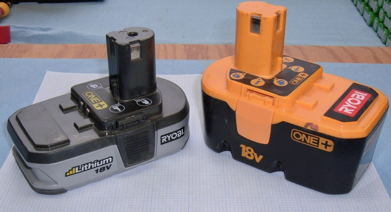
This week, I have a pair of Ryobi One+ batteries - one lithium, one NiCd. This represents the “old generation” and “new generation” of a generation of batteries - they both run in the 18V tools, but one is the old style NiCd, and one is a new style lithium (though, as you’ll see, early lithium).

Join me as I rip into another two packs!
Ryobi One+ 18V Lithium (P103)
I’ll start with the more interesting pack of the two. This is a Ryobi lithium 18V battery, designed for the One+ series of tools.
This particular pack weighs in at 482g (1lb 1oz), and has the standard three conductor interface common to most of the older 18V packs (and, later, I’ll show you how these correspond to the older NiCd packs on the inside).

The old NiCd batteries charge from the top three connections (and I think this one can as well), but there’s also a pair of charge terminals along the main pack (just below the One+ label here). A quick survey of Ryobi batteries and chargers indicates clearly that “It’s Complicated.” Since I don’t have any of these tools, I’ll let you work through the details of what batteries charge with what chargers and work in what tools.
I found 5.80V across the + and - terminals, which is quite low. I don’t know yet if that’s a signaling voltage or the full pack voltage, but it’s definitely not enough to power an 18V tool at the moment. Given how the 18V tools work, I’m guessing just a low pack voltage.

The underside of the pack indicates that this is a P103 lithium ion battery, designed for use with the P113 charger. It’s an 18V pack, rated at 24Wh - or 1.33Ah, using the normal conventions.
I’m sure the operator’s manual says not to do what I’m doing, but, hey. I wasn’t provided one. And I don’t intend to burn this pack up.

The two little vents at the top here remind me of some similar vents I saw a few weeks back on the Rigid batteries. I didn’t think they were important enough to cover in that post, but the Rigid packs have a suspiciously similar vent pattern.
The back of the pack suggests removing the battery from the tool when changing bits out, which I’m sure is observed almost never. It’s certainly a good idea, but as Mike Rowe points out, “Safety Third.” You decide what matters to you on this front.

Ryobi has really changed it up with the screws holding the packs together. Normally, I grumble about the Torx T-10 security screws - but not for this pack! This pack is held together with…
Torx T-15 security screws! Same stupid post in the center. Fortunately, Torx security drivers are easy to find (a pack of 100 assorted security bits is less than $12 on eBay), so they’re no problem for me. With the four screws out, the top and bottom pull apart. For this pack, the batteries stay with the top of the pack - there’s a BMS board in there and the terminals are held in with another screw.

Look at those vent holes on the right! Same as the Rigid pack! And the same blue foam. And the same sort of molded rubber battery holder on the bottom. Hm…

For comparison, here’s the Rigid pack. I think I see a few similarities!

Cells: Samsung INR18650-13Q
The cells remain attached to the BMS on top. On the left, there’s a pair of power switching transistors attached to a chunky pot metal heatsink. In the center, there’s a set of 5 Samsung cells in series. The 13Q designation, for Samsung cells, means 1300mah.
The datasheet for the cells indicates that they’re good for 15A sustained, 30A burst (for 1s). These are definitely power cells, and they’re pretty old. There’s no date code on them, but the datasheet is from 2007, so this is certainly an older pack. With only one set in series, this is a 15A pack that can burst a bit higher if needed to get a drill started (or when it’s stuck, which is probably bad for all parts involved).
Interestingly, the per-cell voltages, from the negative terminal, are 2.35V, 27mV, 0V, 35mV, 3.62V. I’m guessing the BMS draws power from the middle for something, but really, I have no idea why they’re drained in the middle. In any case, four of five cells are scrap (I won’t touch anything below 2.5V), and I’m not terribly interested in the one that might be OK.

The BMS Board
To remove the BMS and cells from the top of the pack, a non-security Torx T10 screw (yay!) in the top of the stem comes out, and then one pries the stem down with a plastic tool (or a metal screwdriver, if your idea of a good time is dead shorts across a battery pack terminals, or you believe they’re so dead as to not spot weld the screwdriver in place).
Unlike last week’s DeWalt 18V pack and the creative T-shaped BMS, there’s nothing up the stem but a few wires and some terminals that all lead back to the BMS board. And a serious sense of deja-vu about this board - I’ve seen that “big diode through a hole in the board” design somewhere else, and I’ve got a pretty solid idea as to where.
You can see the soldered connections for the balancing leading from the nickel interconnects to the board. The circle cut in the negative terminal strip in the lower right is presumably some sort of fuse - if something goes terribly wrong, those thin bits of nickel will melt. And, like the other tool packs I’ve pulled apart, this feels like 0.3mm strip.

There’s not much extra to see with the stem removed - just a region with no components, marked “Optional.” I have no idea what it does, really. Clearly nothing particularly important!

The underside of the board clearly shows that massive diode, a thermal sensor, and the two power transistors screwed to the heatsink.

The thermal sensor is a Uchiya UP72 - same as on the Rigid packs. This is a resistive motor cutoff sensor that is being used as some variety of input into the board microcontroller.

The power transistors (two of them) are IRF1404s - automotive rated power transistors with a 40V max voltage (totally fine) and a 4mΩ resistance when on.
So, using Ohm’s Law, with two transistors, at 15A (7.5A per transistor), each package is dumping a furious 0.2W into the heatsink, and at the peak current of 30A (15A per transistor), 0.9W per transistor. I guess it needs some sort of heatsink, but this seems to fall into the “seriously over-designed” category, to me. Much like most early lithium packs! I love these things - it seems like nobody knew what to expect, so they just went bonkers.

The Wan Nien Connection
I’ve been comparing this pack to the Rigid packs all the way through for a reason - they’re using a BMS from the same company!
On the top: Ryobi. On the bottom: Rigid. Look at the similarities between the BMS boards! They’re not identical, but they’re close. The same company is obviously involved (and even without the Wan Nien label, I’d have concluded the same thing). Same goofy hole for the diode. Same thermal sensor on the back. Same two remote transistors for power. Same layout of the parts! Why, I’d almost say Wan Nien just designed and sold both packs!

Oh, and I was able to read the IC label on this board - it’s a SII S8254A package. Which, confusingly, is a 3S or 4S battery protection IC. For a 5S pack. They’ve got other ICs for 5S packs, but this is clearly labeled as the 8254A. I don’t know if they had spare packages, if they’re ignoring one of the cells, or what’s going on - and I really, really don’t feel like buzzing out the board to work out the details. The no-connect pins don’t seem to connect to anything, but if you want to trace this board out and let me know, I’ll happily ship it to you. It’d be a great reverse engineering project for a college student!
Ryobi 18V One+ NiCd (P100)
The other pack I have this week is an older Ryobi pack - a NiCd (nickel cadmium battery, for you youngsters who don’t know anything older than NiMH) pack.
This pack is somewhat heavier, at 850g (1lb 14oz). I’m sure the capacity is lower as well, but since these don’t come with capacity ratings, I’m left wondering. Or testing. But, this week, just wondering.

Unlike the previous pack, there are no secondary charging connections on this pack - just the basic three connections at the top. Why three? You’ll see!
As is entirely common on the old NiCd packs, the voltage across the pins is zero. This pack is dead.

The bottom contains the information on the battery - P100, 18V. No capacity listed. And, you shouldn’t short the terminals or throw it in a fire. I don’t know why the older batteries don’t list capacities - if anyone knows, I’d love to find out!

Getting Inside
There are no stupid security Torx screws on this pack! Instead, there are some deeply recessed Phillips head screws - much easier to deal with, assuming you have a skinny enough screwdriver (I do).
The whole pack pulls off with the top, leaving the bottom shell exposed. There’s nothing particularly interesting here - just the springs for the release tabs and a pair of vents on either end. No fancy walls for heatsinks, and none of that foam or padding stuff that the early lithium packs have.

The top half consists of the terminals, the stem, and a bunch of cardboard wrapped cells.

A bit of prying on the terminals removes the terminals and cell from the stalk (this is why the stalk is shaped as it is - there’s a cell up in there), and the wiring is pretty clear.
The exposed interconnect is the fuse - throw enough current through this, and it will pop. I don’t actually know what the fuse current is, and I don’t have equipment suited to testing it, though this does seem to be an excuse to buy a 100A+ lab power supply…
The positive terminal (bottom terminal here) is hooked directly to the positive terminal of the stalk cell with a bit of spot welding. The negative terminal (top terminal) has a wire running down to the negative pack connection point. And, the left terminal (“bottom” terminal in normal orientation) has a wire heading down to a something taped to a cell!

That “something” is a JRMB45 - which, with a bit of searching, is a Battery Thermal Protector! This opens at 45C, give or take, and blocks charging. As I understand it, the battery is drained through the always-connected +/- terminals, and is charged using the center (thermally protected) terminal to avoid charging when too hot.
I’m not sure I like the thermal protection placement, though. The protection gizmo is sitting on the very outside of the pack, where it is only exposed to one cell, and has the case on one side to cool off against. The core of the pack can be very significantly hotter and this won’t trip charging off. I assume that this was designed into the system, but the difference in pack temperatures that will trip this between summer and winter has to be huge. I may see if I can detect a capacity difference between the center and outside cells if I test them (I will recharge a dead NiCd cell if it holds a charge - they’re a lot safer to recharge from dead than lithium ion, which I won’t bother below 2.5V).

Cells & Wiring
These cells are “DGH26NH” cells. I can’t find a thing about them, but they’re obviously Ni-Cd, and should be recycled.
Why is the pack stone dead? NiCd has a really high self discharge rate (around 10%/month), so sitting for a year will drain it completely.

If you need the cell interconnect layout for a rebuild on this style of pack, here you go! The cell below the stem cell is the center cell on the right.


Final Thoughts
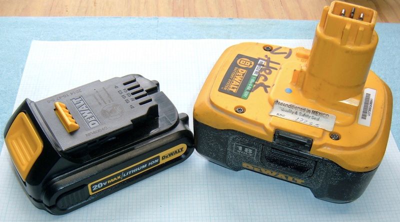
It’s interesting watching the development and evolution of tool pack design. The NiCd packs were dead simple - a bunch of cells in series, a basic thermal protection cutoff, and that’s it. However, they were designed around a particular form factor cell - the stem is specifically designed to fit one of the normal NiCd cells, and that left them unable to easily change things (creative T-shaped BMS boards or just leaving the space empty). That’s a real downside of designing around a cell. The newer packs (like the DeWalt 20V Max) can change cell form factor (as with the change from 18650s to 20700s) without having to redo the connections or waste space. It’s a useful evolution in pack design - DeWalt could just as easily do something with pouch cells if they felt like it in the 20V Max series.
The early lithium packs are absurdly complicated. They all have full battery management systems in place, and this keeps the pack in good shape - at least until the BMS drains the pack when it sits for a long time.
What I find fascinating is that two packs, by two different companies, are almost identical on the inside - and have a custom BMS board by the same company. I suspect they’re just custom designed by Wan Nien for the company. Anyone know details of this process?
Coming back around full circle, the most recent packs (like the DeWalt 20V Max 6.0Ah pack I pulled apart a few weeks ago) are back to “dumb packs” - the interface board just connects the cells to the charger and the output terminals, and all the smarts are in the charger and tool. This newer method should be a good bit more reliable - and, usefully, a lot more hobbyist friendly if you want to use them for something else.
Next week, I’ll wrap up my current wave of tool pack teardowns with a bunch of NiCd packs, then go onto something a bit different!
Comments
Comments are handled on my Discourse forum - you'll need to create an account there to post comments.If you've found this post useful, insightful, or informative, why not support me on Ko-fi? And if you'd like to be notified of new posts (I post every two weeks), you can follow my blog via email! Of course, if you like RSS, I support that too.


