
Another week in May, another pair of tool packs in my series of tool pack teardowns!
This week, I’m back to DeWalt with a 20V Max 1.3Ah, and an older 18V “Nano Phosphate” pack - which has the weirdest cell layout I’ve ever seen. The date code says 2007 - so this is another example of an early tool pack in the “Working out the details” phase of lithium tool packs.

Join me as I rip into another two DeWalt lithium battery packs!
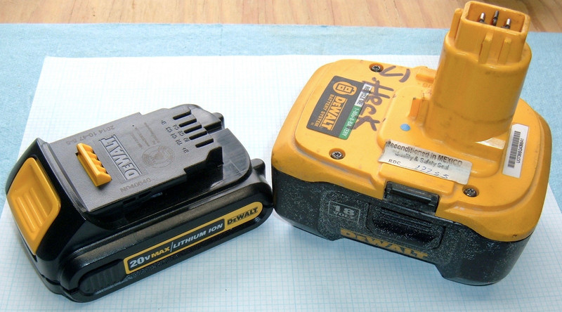
DeWalt 20V Max 1.3Ah Battery (DCB207)
At this point, I’m getting pretty familiar with the DeWalt 20V Max series. I’ve pulled apart the 3.0Ah pack, torn apart the new 20700 based 6.0Ah pack, and successfully fried an egg with the 6.0Ah pack.
This is the smallest of the 20V Max packs I’ve seen, and it’s cute - plus, very light, at a mere 11.8oz (336g).

The bottom of the pack informs me that this is a 1.3Ah battery, 26Wh (which it isn’t - they do the math on a 20V pack voltage, or 4.0V/cell, which is nonsense, and a more sane calculation at 3.7V/cell gives 24Wh), and that this is a “Type 1” battery.
I think I’ve finally worked out what “Type 1” and “Type 2” batteries are - it relates to current handling! This battery can’t push out as much current as the larger packs, so it only works in certain types of tools (or the tools restrict power with it).

The terminals are the standard DeWalt 20V Max terminals - B+, TH, ID, C1, C2, C3, C4, and B-. The end terminals (B+ and B-) are double height and are the main output terminals - the full pack voltage is always present on them. C1 to C4 are the cell group balance terminals - so B- to C1 is the first cell group, C1 to C2 is the second, etc.
TH is a normal 10k/25C thermistor - but connected to the positive terminal. If you want to read the resistance like a normal person, read between B+ and TH. If you want to build yourself a voltage divider for thermal cutoff reasons, put your known resistance between B- and TH, and do the math to figure out when you should shut down. These really are great tinkerer packs!
The resistance between ID and B- is only 320Ω on this “Type 1” pack - on my “Type 2” packs, it’s 800Ω! So, ID to B- resistance corresponds to the pack type at some level.

Diving In
The screws are the normal DeWalt Torx T10 security screws, which I still think are complete nonsense. In any case, remove four screws and the top comes off. The latching mechanism is the same as on all the other DeWalt 20V Max packs (unsurprising, since they have to all hook up to the same tools), and, annoying, the battery interface board is potted with a bunch of goop.

The interface wiring is the same as on all the other 20V Max packs - the battery pack is wired directly to the B- and B+ terminals, which are double height and a different material from the rest of the pack terminals. This means that if you shove spades in B+ and B-, you get power! Really useful as an interface to the pack, and dead simple, but it means you have to do low voltage cutoff and charge balancing yourself.
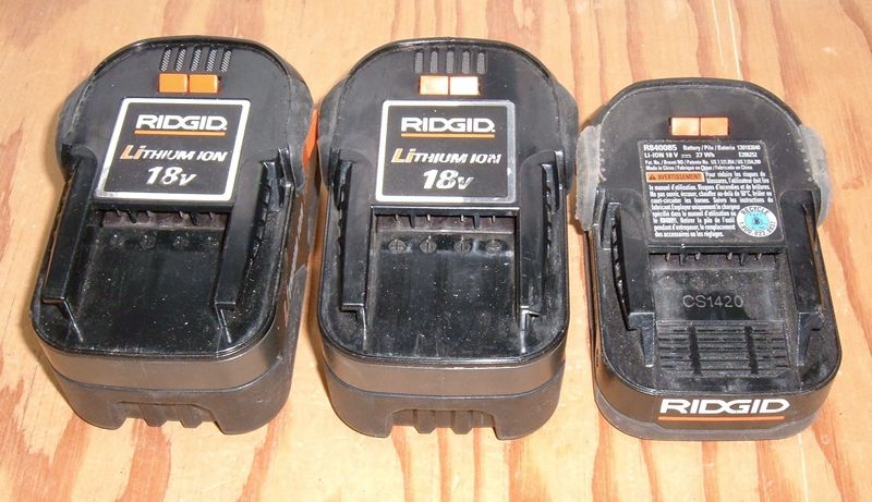
It’s interesting to contrast this approach to battery management (entirely external) to the more complex BMS boards in the older Rigid packs and the pack I’m tearing down next. It’s pretty much the “Hobby LiPo” management style - the battery does nothing, and the charger and device being powered handle the details.
In theory, it’s a good idea, but you do end up with situations like this pack, where for utterly unexplainable reasons, two cells are totally dead.
Going from negative up, I get cell group voltages of 4.04V, 4.04V, 3.67V, 0V, 0V. I have no idea what ate this pack or why, but it’s toast. Recharging lithium from 0V is a really, really bad idea, and not one I’m willing to play with.

With a bit of prying, the core comes out of the bottom of the pack. There’s no fancy rubber cushioning in here, just some plastic holders. It seems to work well enough!

The pack wiring is quite visible at this point - the exposed wires go from each cell to the balancing leads, and the main positive and negative leads are soldered in place. The interface board (it’s not even a BMS) is pretty simple!

The Cells: Samsung INR18650-13Bs
Conveniently, I can read some of the cells in their holder - they are Samsung INR18650-13B cells, which are 1300mah cells (1.3Ah) rated at a 25A peak discharge.
The “5DO5” below SDIEM is a date code - and BatteryBro has an awesome decoder page! These cells work out to a production date of Sat Jan 05 2013 - which means this pack is 4 years old. Slightly outside the three year warranty, unfortunately.

I can’t say for sure, but I think these packs are hand assembled. Tolerances are good, but not quite what I’d expect of a robot welder - and everything is inspected by a person with a marker afterwards.
The tabs feel like about 0.30mm, and the slits in the middle help with the spot welding process. Nothing terribly exciting here.

That’s about it for this pack - nothing more to see. It’s a 5S pack, good for 25A. And this one is oddly dead.
DeWalt 18V Nano Phosphate Battery (DC9180)
The next pack I’ve got is an older DeWalt 18V pack - from 2007, if the date stamped on the pack is to be believed. This uses the older style “Shove it in the handle” style of connection, and is a replacement for the old NiCad packs.
I suspect this battery pack was used by a painter at some point - no idea why…

The 18V DeWalt tools use a two pin connector - visible here. There’s no voltage at all present on it, which probably means a totally dead battery inside.
Interestingly, this pack has a “Reconditioned in Mexico” sticker, with no date. I don’t know what this means - the insides look factory to me, so either it’s an amazing reconditioning operation, or that means they pulled it open, charged the cells, and sold it again. No idea, unfortunately.

The usual warnings and labels are underneath. This is a DC9180 18V Type 1 battery pack, and that’s about it for the useful data underneath.

The marketing blurb on this reads, “Nano Technology” - “Powered by nano phosphate lithium ion.”
If I had to guess based on this, I’d suspect a lithium iron phosphate cell on the inside. Nano? No idea - probably something a marketing person dreamed up after reading a datasheet.

Finally, the top of the pack has what looks like a date code on it - “2007 30 U0”. This would imply, generally, that the pack was built in 2007, and either built on the 39th day or the 39th week. In any case, the pack is about a decade old - so, time to see what makes it tick inside!

Diving Inside
With the four Torx T10 security screws removed, the top starts pulling free. There are some locator pins on each end that I haven’t seen on any other packs, and an interesting little ribbon cable, which is for balancing the cell groups. I’m pretty sure I didn’t damage the cell insulation, though, which does support the theory that someone has worked on this pack before.

The top comes slightly clear of the bottom, then the cell pack comes clear of the black bottom case - and what a weird cell pack this is! All sorts of cells going all over the place, bent nickel strip… this is a funky layout, but exists to fit in the form factor of the old NiCad cells.

There are three cells across the top and bottom, two in the center, and two on each end - for a total of 12 cells. This would imply a 2P6S pack - two cells in parallel, six of those groups in series. For that to work with an 18V pack, it’s pretty certainly lithium iron phosphate. Which I’d guessed based on the outside of the pack.

There’s a “something” in the stalk of the pack that inserts into the tool, and it’s screwed in. I can’t actually get to the screws without removing the battery pack, sadly - so I’ll have to do that.

The main power wires are very nicely soldered into holes in the positive and negative tabs, and have a double layer over the top (presumably to help prevent insulation rubbing). The wires are only about a 14 gauge wire, though. That’s not my preferred wire gauge for the current this pack can source, but the losses on this short run are small enough that it doesn’t really matter.

The Cells: A123 APR18650M1A 1100mAh LiFePO4
The cells are A123 lAPR18650M1A cells - with a handy datasheet if you’re curious. This is where the “Nano” comes from in the pack name - the datasheet claims, “A123Systems’ lithium ion rechargeable APR18650M1A cell is capable of very high power, long cycle and storage life, and has superior abuse tolerance due to the use of patented Nanophosphate™ technology.”
They’re rated for 1100mAh (LiFePO4 is lower energy density than a lot of other chemistries), 30A (but very excellent power density), and “over 1000 cycles” at 5C to 100% DoD - which is a 55A discharge for testing! I love lithium iron phosphate for a lot of reasons, and these are them. Unfortunately, the energy density isn’t great. You get about 3.6Wh per cell on these, vs 5.5Wh on a newer power cell, or 12.5Wh on a modern energy cell. But, seriously. The discharge current on these is bonkers.
What this works out to, in a full pack configuration, is a capacity of 2200mAh, a nominal voltage of 19.8V, a fully charged voltage of 21.6V, and a drained voltage of 12V. The total pack capacity is around 43.5Wh, which is respectable, and utterly insane for 2007.
I can’t manage to find a date code reference for these, but the pack was built in 2007, and there are a few “07s” in the data region, so I’d guess these are original cells. Also, I see no evidence of anything post-factory in here, other than a few nicks. Someone probably just attached a charger to the pack - which I may actually consider trying at some point. LiFePO4 is pretty well behaved!

The BMS
There’s something crammed up into the stem of the pack. This something has the power feed going into it and a ribbon cable coming out - so it’s almost certainly a battery management system (BMS).
And that’s a really weird shape for a BMS, so it’ll be interesting to see what comes out.

I removed the two black headed screws, tried to pull it out, couldn’t manage to get it to move, and then decided to use a precision technique known as “percussive disassembly.” That sounds much fancier than “Stick a screwdriver on top of it and smack the handle,” which is what I did - successfully!

There’s a BMS in that stem! This is a “T” shaped BMS, designed to fit in the stem. That’s cool.

I haven’t seen anything designed quite like this since some of the interface boards in my old Proliant 6000. Quad Pentium Pro 200s, a gig of RAM, a huge SCSI array clattering away, and some spiffy case mods, like a cold CFL light for the drive bays and a serial LCD console to show CPU use. It was massive, power hungry, hot, loud, and about 150% awesome. My dorm room was an interesting place - try explaining to someone in the early 2000s that literally nothing of the half dozen loud and annoying computers in your dorm room ran “Windows,” and that your bank of 3 “SGIs” was controlled by a single keyboard and mouse, even though they were three different systems with totally separate monitors.
For a while, I had this Proliant in an OpenMosix cluster with a Pentium 4 in a Shuttle case. I learned much about compiler options, because otherwise things won’t migrate (Pentium 4s have a few more instructions than a Pentium Pro). I learned so much messing with things for the sake of messing with things…

Oh. Right. BMS. Tool packs. This BMS has two metal “wings” going up the sides connected to the heatsink for the power switching transistors. They generate a good bit of heat, even if they’re low resistance when on.

With the heatsink wings bent out of the way, the BMS boards are visible! Like the other tool pack BMS boards, this is hit with a conformal coating - a spray on coating that protects the board from moisture, dust, metallic grit, etc. There’s no reason to not have it at this point in time. Even a decade ago, this has the coating, which is excellent.
I’m not sure what the top four transistors are for - the main power transistors are along the right in this photo, but towards the bottom, there are six little transistors (or what look a lot like transistors) - and this is a 6S pack. There’s probably a reason!

On the other side, the reason is clear! There are 6 small resistors behind the transistors. This means that the BMS is a bleeding BMS - it will drain power from the “most-full” cell group to ensure everything is balanced.
And there’s a controller chip on here - which, with the right light, I can identify as a MSP430F1232.

What on earth is a MSP430F1232?
It’s a Texas Instruments microcontroller! And a pretty nice one, at that! To quote the product information page, “16-bit Ultra-Low-Power Microcontroller, 8kB Flash, 256B RAM, 10 bit ADC, 1 USART” - which is very, very impressive for a battery pack.
The datasheet is a fun read if you’re into microcontrollers. It’s nothing fancy, but… wow. A lot more guts than I expected in a BMS.
I assume it’s using a microcontroller because the design of this pack predates dedicated BMS ICs, and this was the best way they could find to do the pack management and balancing. Unfortunately, microcontrollers do draw a bit of power, and I expect the BMS draw is what killed this pack over time. Shoving the microcontroller based BMS up in the stem is definitely an interesting way to solve this particular problem, and I bet the engineers involved had a lot of fun working within the constraints they were given!
Final Thoughts
It’s interesting to compare “Old DeWalt Lithium” and “New DeWalt Lithium” pack designs here. The old design, because it had to handle a charger and tools designed for older NiCad packs without a BMS, had to do all the work of maintaining a lithium pack internally with the BMS. I’m not sure what the power draw on the BMS is, but it’s non-zero, and that will eventually kill a pack that sits without being charged for long enough. There’s 8760 hours in a year, so a 1mA draw will kill a pack in under a year, and even uA level draws will kill a pack in a few years for a typical pack (combined with the normal cell self discharge).
The newer 20V Max packs are much dumber on the inside - they rely on the charger to do the balancing and the tools to do the low voltage cutoff. This allows for a cheaper, more reliable pack (though I don’t understand why I keep seeing totally dead cells on them). It’s an interesting evolution in design, and it’s quite obvious pulling packs like these apart, back to back.
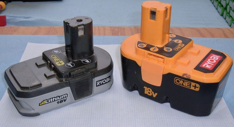
That’s it for this pair of packs. Next week, I suffer deja vu with some Ryobi packs!
Comments
Comments are handled on my Discourse forum - you'll need to create an account there to post comments.If you've found this post useful, insightful, or informative, why not support me on Ko-fi? And if you'd like to be notified of new posts (I post every two weeks), you can follow my blog via email! Of course, if you like RSS, I support that too.


