One of the problems I have on my property out here is burrowing critters. We have voles, rock chucks, and gophers - at a minimum. There might be more I haven’t found yet. I’ve attempted to deter them from areas we care about (like the garden) with some little solar “burrowing critter” emitters. In theory, they make enough annoying noises under the ground that the critters just go somewhere else.
Maybe you’ve seen them - a solar panel on a stick that you wedge in the ground. A 4-pack on eBay runs about $25, maybe a bit less.

Do they work? Hard to say. They’re faintly annoying to me, but I’m not a gopher. Would a gopher find them annoying enough to stay away from the garden? Maybe. Ask me in a few years.
How do they work? Well, that’s a question best answered with a teardown - and that, I can do!
The Solar Rodent Repeller
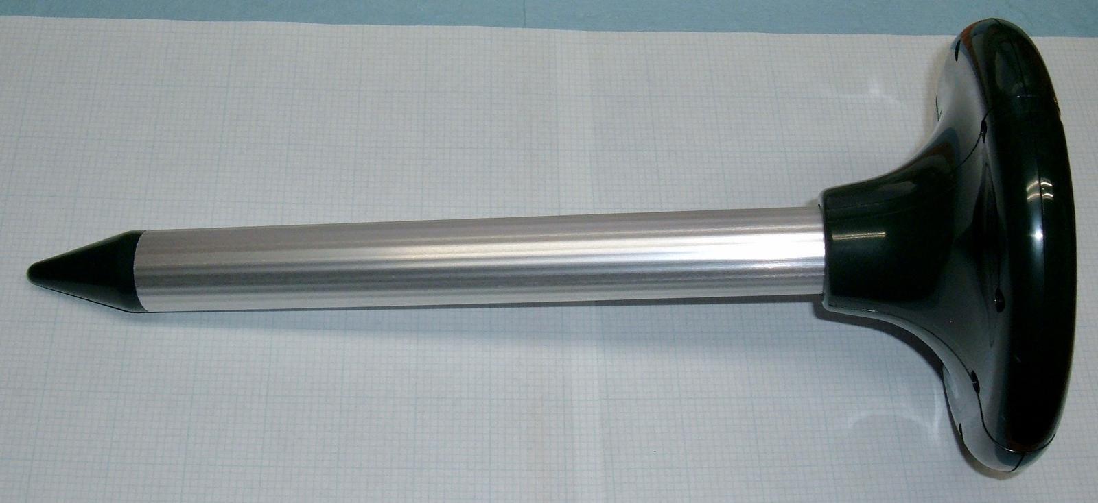
Assemble the unit as it comes out of the box, and you get something that looks roughly like this - a metal pole with a plastic point on the bottom, and a round top with a solar panel. Presumably, there’s a battery in there, because these whine intermittently in the dark as well (we have one already, I ordered more… and felt like taking them apart because that’s what I do).
But what’s in it? What makes it tick? What sort of interesting Chinese-designed electronics are in this gizmo? For that, I’ll have to take it apart.
The Point
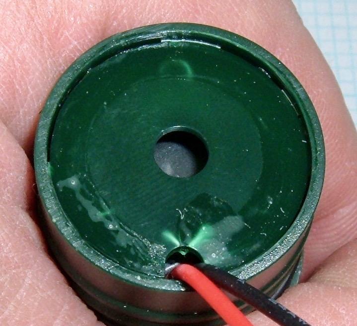
The bottom is a plastic point you jam in the soil, and it has wires leading into it (presumably to power the noisemaker). There are two O-rings on the side to help seal the metal tube. I can’t say I’d trust this thing indefinitely in wet areas, but the one in our garden is still fine, so… it’s probably fine against most water. If you’re in a really wet area, you might want to throw some additional sealant in here before putting it in the pipe. Some GE Silicone II should work fine, or… really, whatever you have laying around. Just goop it up before assembling and you’ll keep the water out nicely.
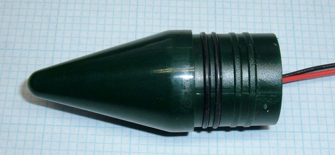
The wires head into the end, and there’s a small plastic disc glued in place to keep the buzzer from flopping out. It’s not very well glued in place, though, so it pops right out with a bit of convincing from a small screwdriver.
The Buzzer
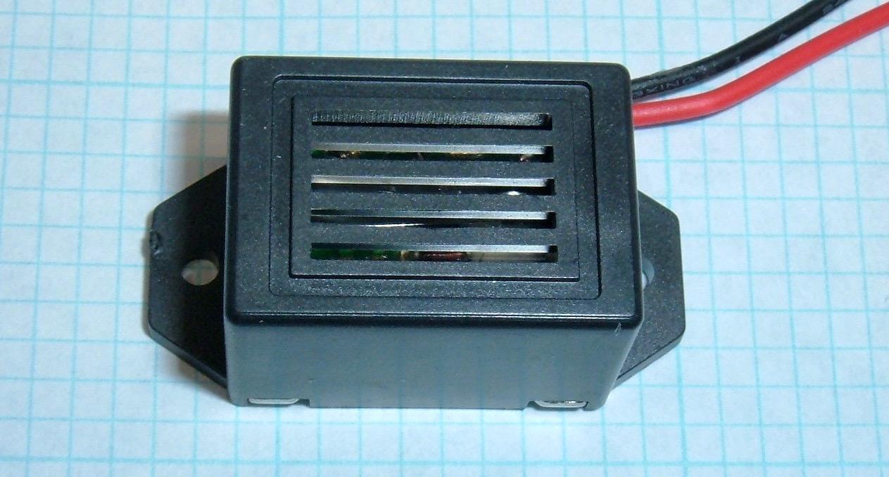
Inside the point, there’s a little black plastic box. This is the buzzer, which creates both noise and vibration to annoy burrowing critters nearby - in theory. It’s hard to see in the picture, but there’s a clear plastic sheet under the grille.
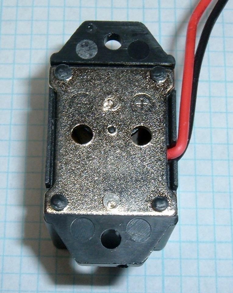
The back has a metal cover and the ever-common “melted plastic blobs” used to secure covers on really, really cheap things. Anything faintly sharp will remove these. I use a pair of wire cutters and just chop the whole mushroom off by scraping sideways over the post.
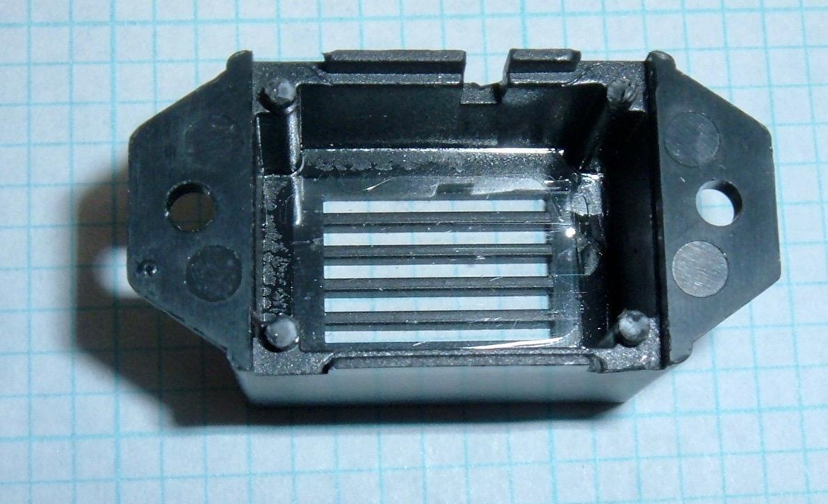
With the guts out, you can see the case. The clear plastic bit already shows some stress damage, and I have no idea how long it will last in the field, but… again, we’ve got one, it’s a year and change old, and still making racket, so it’s probably fine.
The removed guts are a buzzer of some sort. It faintly reminds me of the old style flexible metal strip buzzers from the 50s and 60s, but it’s not - there’s no actual contact involved in the pulsing of the electromagnet. It detects the magnet position via feedback, through some fairly simple circuit (I haven’t worked out details), but it happily buzzes the strip back and forth when voltage is applied. The electronics consist of a small transistor and diode (at least, I assume the L5 gizmo is a transistor - it’s got three legs). It starts buzzing around 1.1V and 20mA, and pulls about 40mA by 3V - it’s not using much power at all. I didn’t push the voltage past 3V, as it normally operates around 2.7V and I didn’t want to burn it out.
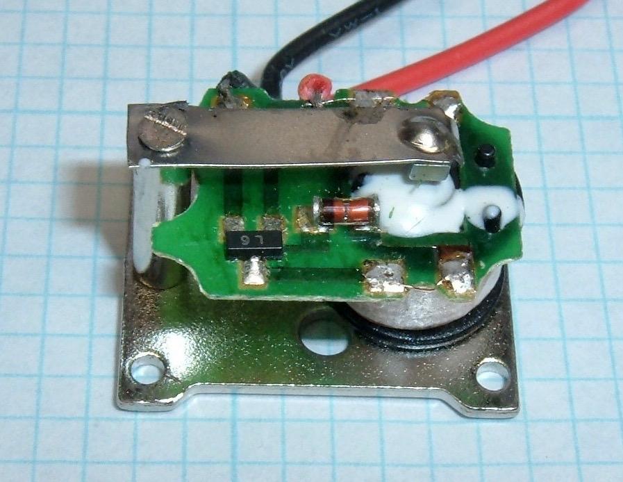
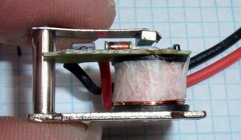
From the side, you can see the electromagnet, a small magnet (or hunk of metal?) on the spring strip, and the components on top. Nothing terribly complicated, but it works nicely. When power is applied, the metal strip buzzes back and forth, and if the black case is installed, it makes quite a racket banging on the clear plastic window.
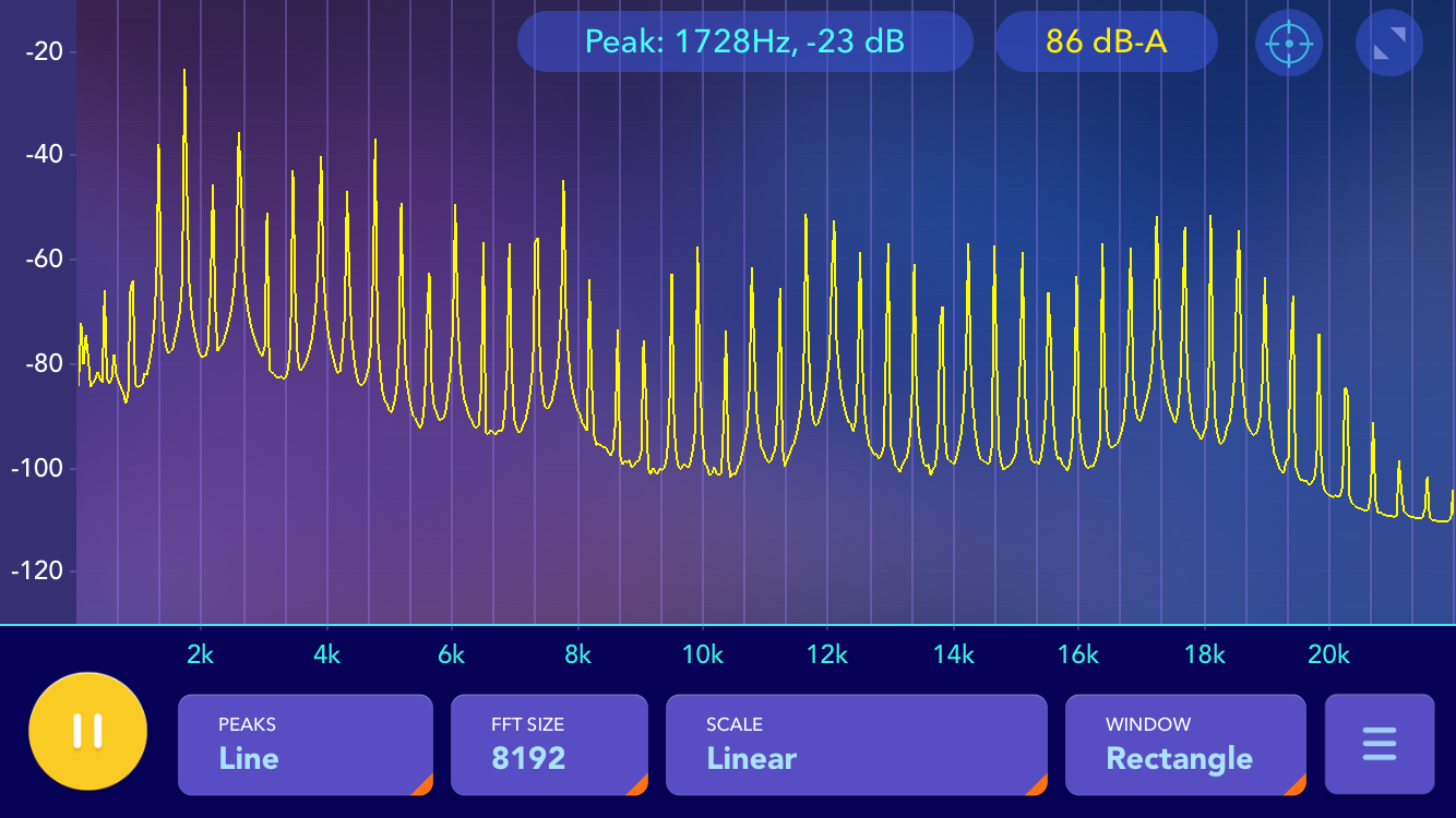
What does this racket look like if you stare into the frequency chart? A useful little spectrum analyzer on my phone answers that question: It looks like the FFT of a square wave, give or take. There’s energy throughout the spectrum, heading up into the ultrasonic (I’d wager the drop after 20kHz is more my phone’s mic and sampling system quitting), and a surprising amount of it. As a human, this is a genuinely irritating noise. Were I a gopher, I’d probably also find this very annoying!
The Power Top
With the details of the buzzer end mostly worked out, the only other interesting part is the top - the bits that take power from the sun, store it, and send it on down the way. Will there be a cheap microcontroller in here? Will it be some analog abomination? What sort of battery do they use? The world eagerly awaits the answers to these, and more!
But, seriously, it’s cheap and Chinese. There’s no microcontroller in there. That’s not how they do stuff like this, which is part of why I find these gizmos so interesting.
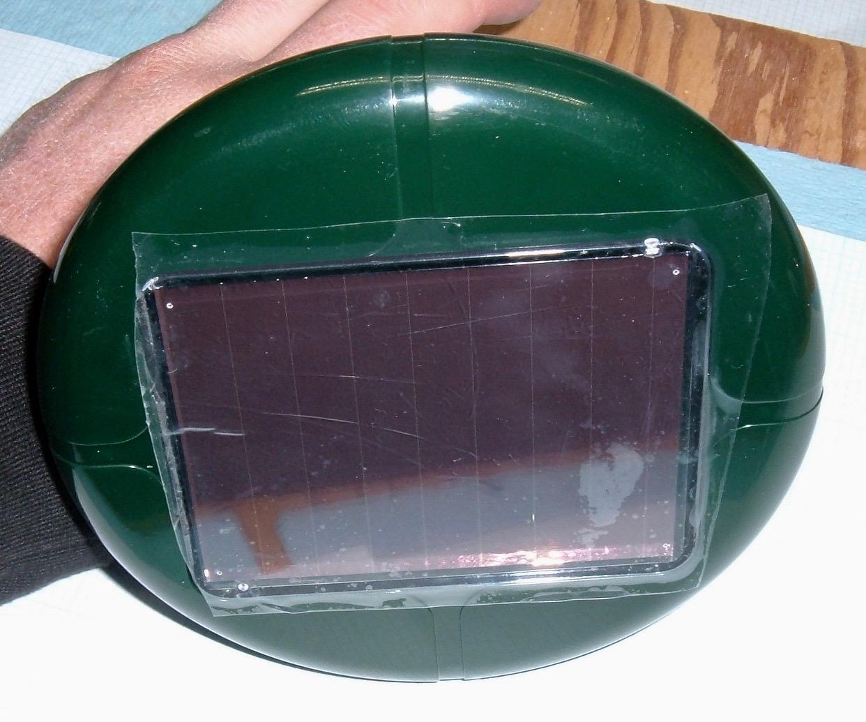
The top comes with a large solar panel in a round disc. Why round? No clue. It’s symmetrical, at least.
The underside has a wire connection, and a bit that plugs into the tube. This end doesn’t have O-rings, but it’s also not below the ground level - you’re not supposed to bury these things all the way in, though the desired depth isn’t specified. I bury them 6-8” in.
Around the edges, you can see the four screws at the 45 degree points, and… fake screws molded in?
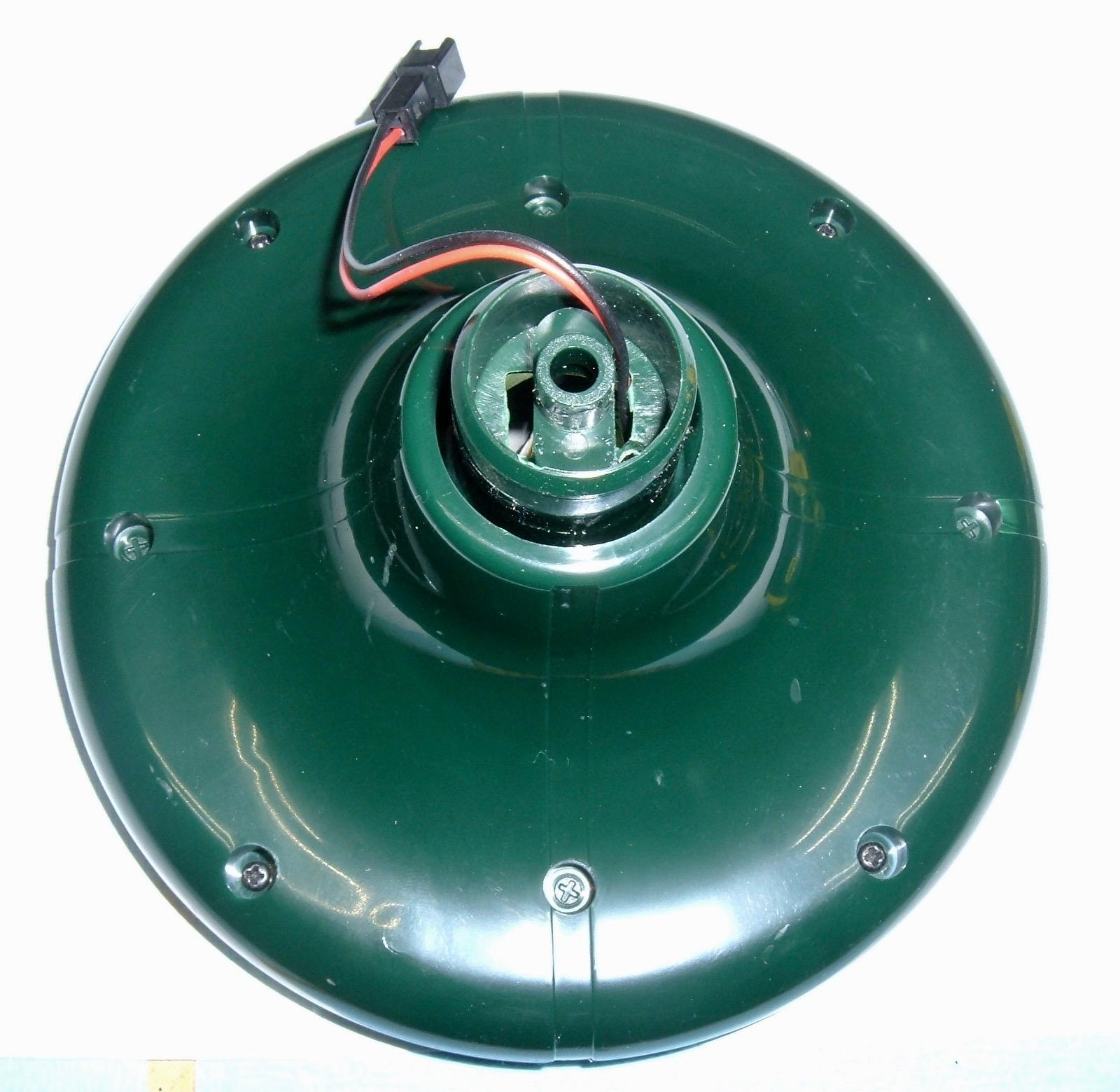
Yup. Fake screws. There’s nothing for a screw to bite into below these, so they’re just decorative, fake screws. On the bottom of a cheap garden gizmo. I can only assume these parts are used for other products as well, because the alternative is even more baffling.

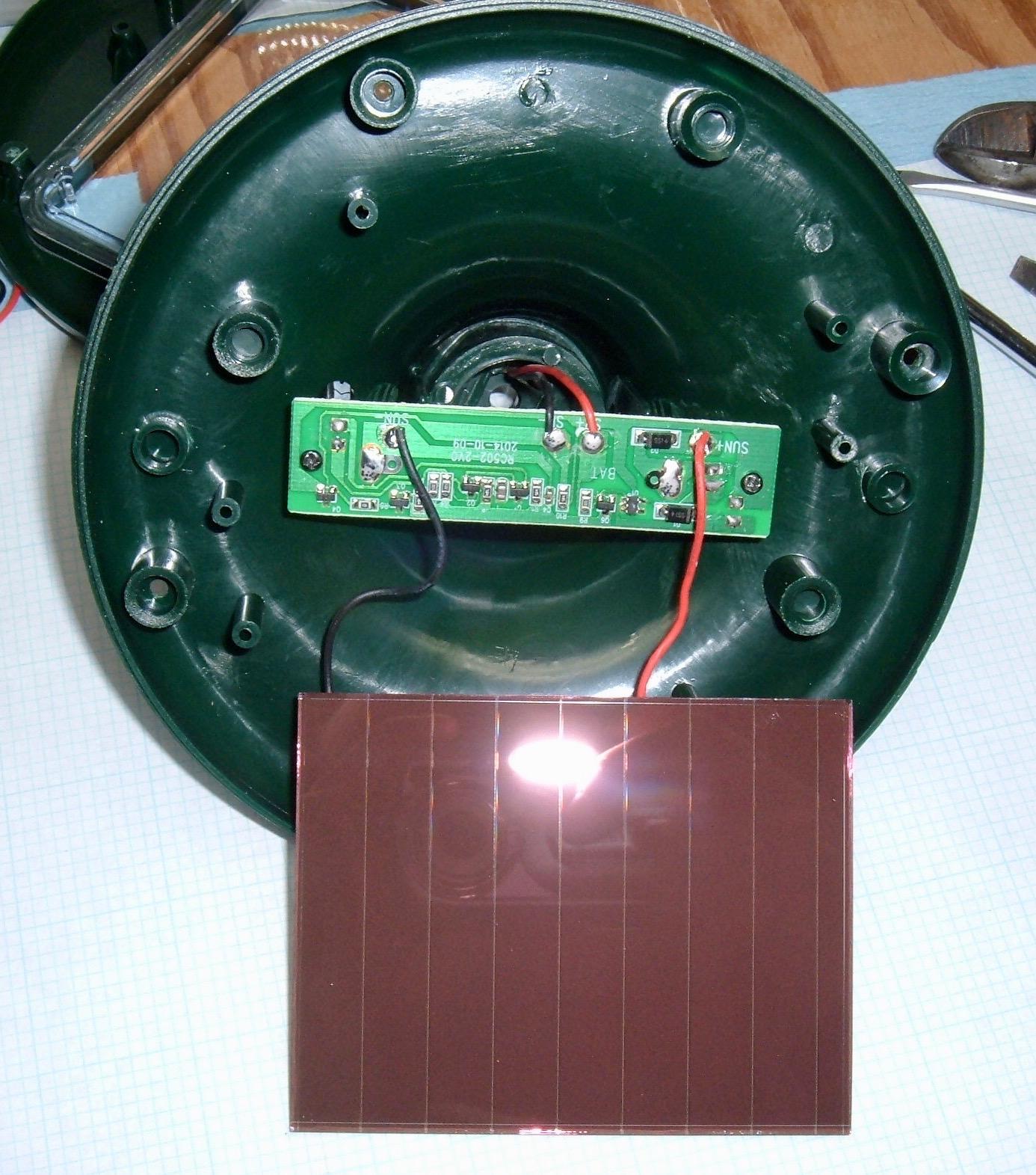
With the screws removed, the top pops off and the guts start falling out. The solar panel is actually a massive glass unit - it was not at all the cheap panel I was expecting! We’ve got a controller board with no signs of a microcontroller - just some basic analog electronics and a few transistors, plus whatever’s on the other side.
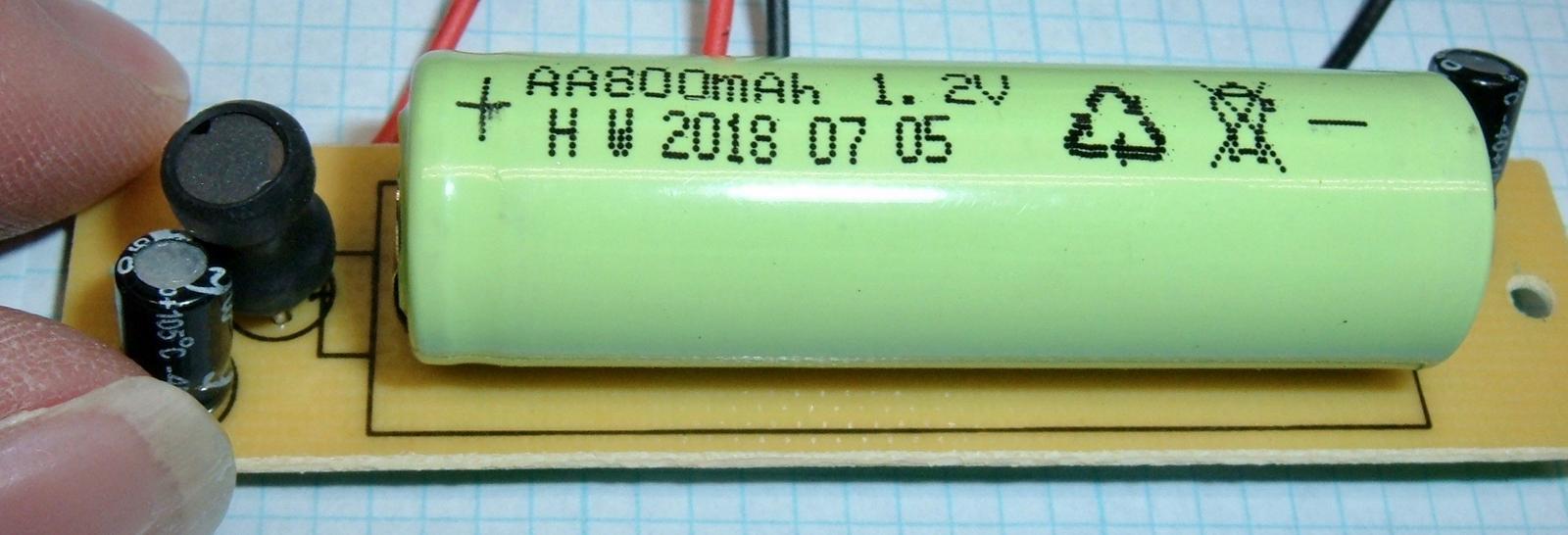
The other side contains a battery (800mAh 1.2V - so either NiCd or NiMH), a pair of capacitors, and… an inductor? I was not expecting that. Where there’s an inductor and a capacitor, there’s almost certainly a boost or buck converter. This requires more poking!
The battery is actually a moderately competent looking bit of hardware, and not the button cell I was expecting. I’m not sure if it’s NiCd or NiMH - they’re both similar chemistries, and similarly behaved, and I don’t know a good way to tell the difference if the label has no information. However, it’s a quite recent battery, by the build date, so I’d wager on NiMH.
The back of the board shows the lack of microcontroller quite clearly. It’s diodes, resistors, capacitors, transistors, and one slightly weird chip (above and slightly to the right of the left battery terminal - 5 leg parts are unusual). Part numbers are mostly meaningless, so I’ll have to dive in a bit more.

The Solar Panel
The solar panel from this unit is not at all what I was expecting. It’s an ASC090070, whatever that means, but it’s a thin layer on the back of a rather thick sheet of glass - and it’s not normal cells, either.
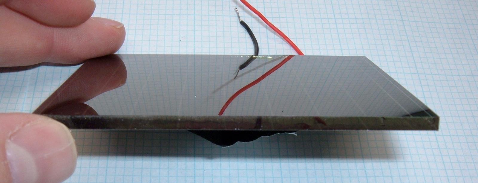
As near as I can tell, the panel is some variant of amorphous silicon - a thin film solar technology. While the efficiency isn’t as good as normal mono- or poly-crystalline panels in full sun, they make up for it by having better efficiency when partially shaded, or in dim light. Calculator solar panels are often of this construction, since they generate a useful amount of power indoors. For garden use, this is probably just fine - they can deal with indirect light coming through plants.
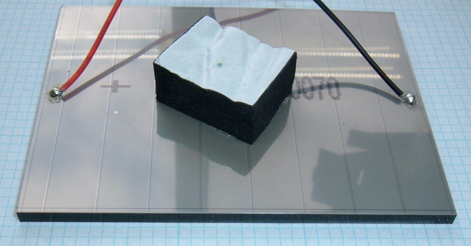
What’s weird is that this is a very, very high voltage panel for the battery cell. I removed it from the board to do some testing, and I’ve got more questions than answers, actually. Open circuit is 6.8V, and the short circuit current is 50mA (in the winter, aimed straight at the sun). That’s bare, without the plastic cover over the top, but it’s about a 0.3W panel, give or take - except that if I’m not mistaken, it’s never actually run anywhere near that high. It seems the panel is dragged down to the battery voltage, so it’s operating at the cell voltage (1.2V), or around 0.06W. This is not a high power system.
This whole thing is just a bit kooky, and I’ve not yet figured out the inductor - so, the investigation continues!
Charging Circuits
I find the Chinese approach to engineering quite fascinating, because it’s totally and completely different from how I approach problems - but, in many cases, it works almost as well, for a fraction the cost. The charging circuit here is one such solution.
It’s not so much a charging circuit as “A solar panel, hooked directly to the battery, with a diode.” Literally. Sun+ (lower left) goes to a diode, which goes straight to the battery positive terminal (the metal loop sticking through with a large solder glob). Sun- (lower right) is tied directly to the battery negative. There is no regulation here, beyond the diode (to prevent panel backfeeding from draining the battery).

The catch is that, with the selection of a NiCd or NiMH battery, and proper panel selection (which they’ve done), it works fine. You can more or less safely overcharge NiCd/NiMH at a C/10 rate (so, for this supposedly 800mAh cell, 80mA), and they tolerate it. Throw in some shading, inefficient panel positioning, and you have a lower charge current. I’d be surprised if this hits 30mA when installed normally. So, you simply don’t bother regulating the charging (except to prevent the battery from draining into the panel), keep the charge current low, and you’ve got something that mostly works to keep the battery charged without damaging it, for a very low circuit cost.
I’ve tested this by attaching the leads to one of my buck converters and tossing 50mA at the battery for a few days (during the day when I’m out in my office). The voltage at the charge terminals rises to about 1.73V, with the battery being around 1.5V (after diode losses), and things just sit there. It’s a perfectly valid way to charge nickel batteries. The rig started out charging around 1.4V, rose up during charging, and sat there for hours and hours. There just aren’t enough amps from the panel to overcharge the battery.
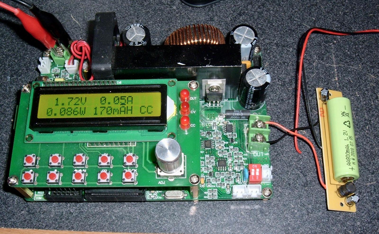
NiCd and NiMH both have a very wide operating temperature range (-20F to 100+F), tolerate overcharge, and don’t really mind being fully discharged (it’s not great for them, but it doesn’t destroy them like it does for lead acid or lithium). Any sort of outdoor solar product is almost certainly using one or the other.
Now, why you’d use a 6V panel for charging a 1.2V battery, when you’re never letting it run above about 2V? I have no idea there. Maybe this was the cheapest panel they could find that met their current requirements. Normally, “non-regulated solar charging” doesn’t go for comically absurd panel voltages like this. I’d assumed that I’d find 3 cells in series based on the panel size, but… nope. Perhaps there’s some benefit of a thin film panel being over-voltaged for the loads I’m not aware of (in terms of shaded/low light performance).
Boost Converter Circuit
The battery is a 1.2V battery - but the buzzer needs about 3V (I measure 2.8V on the terminal going to the buzzer). How to solve this? A boost converter! The inductor and capacitor pair I saw are a boost converter for the output side. As near as I can tell, the converter is driven by the only complex-looking IC on the board - a L33M, to the right of the diode in the top left. It’s the only thing more complex than a transistor (5 legs, woo!), and it’s tied over to the inductor and capacitor.
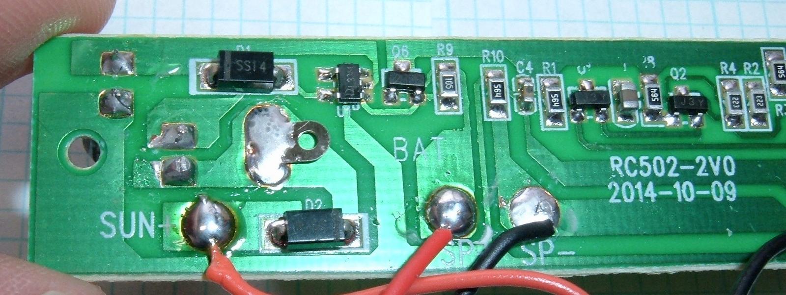
I can’t find this chip anywhere on the internet, so it’s probably a Chinese Special. However, I was still curious about the frequency it ran at. In other words, “I have an excuse to pull out my Very Fancy Digital Oscilloscope.”
A bit of fiddling around later, and I’ve got a nice trace of the voltage over the inductor while the output is active. It’s what one would expect, a nice(ish) square wave, and I’ve got my answer for frequency: 200kHz. Well above audio ranges, and it allows for some fairly small components.
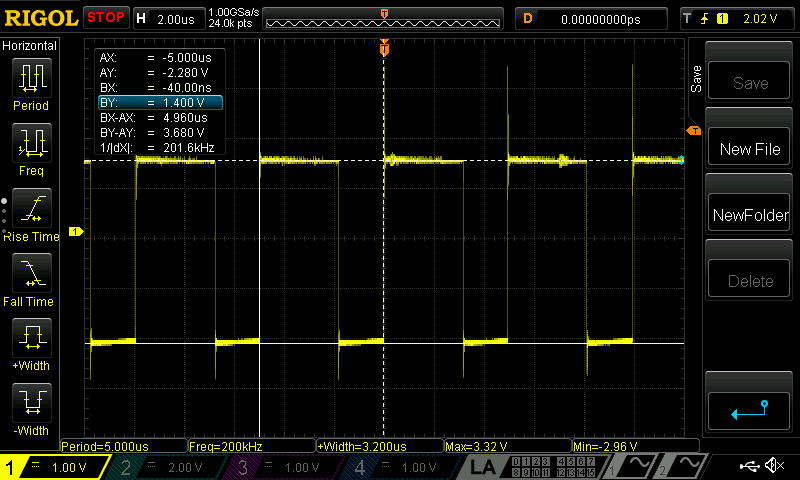
When the buzzer isn’t running, the boost converter isn’t running continuously. The controller seems to pulse it as needed to maintain the voltage on the output rail - I’d love to find a datasheet for that chip to see exactly what it is.
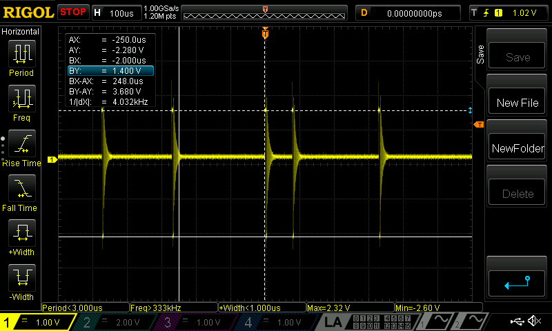
Zooming in on one of the pulses in voltage hold mode, check out that ringing… it doesn’t seem to do any damage to anything, though. The ringing voltage isn’t radically higher than the normal switching voltages, so beyond wasting some power, it’s fine. Unlike some other gizmos I’ve looked at…
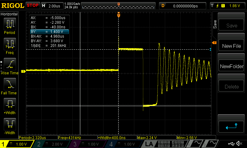
Not much to it, really. Just a simple regulated boost converter that kicks battery voltage up to what the buzzer needs - around 2.8V, give or take a bit. I assume it’s cheaper than an extra battery cell.
The Timer Circuit
The timer circuit is similarly analog. The capacitor on the other end of the unit is part of a timing circuit, and measuring the voltages across it, you can see the repeating pattern (ignore the fuzz in some of the signals - I was having a hard time keeping the negative clip in perfect contact). It’s about a 25 second cycle. When the buzzer is on, the voltage rises until it cuts off the output, then the voltage drops until the output turns on.
You’ll note here that the lowest voltage across the capacitor is about -0.4V - which, for an electrolytic capacitor, is probably OK. I’m surprised by that, but it doesn’t look like they’re violating any real limits by doing it.
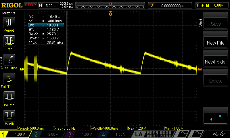
Zooming in on a rise, the buzzer is on for roughly 1.5 seconds.
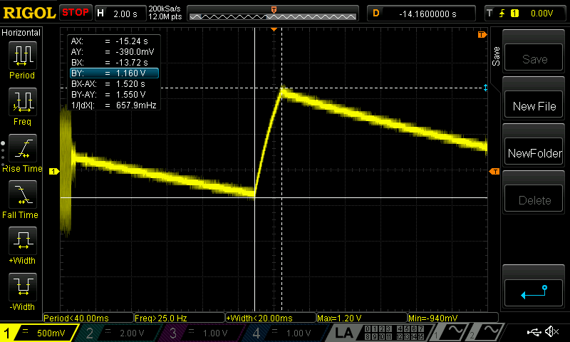
Using the power numbers from above (2.8V, 0.04A) means the on-power is ~100mW, and the duty cycle (1.5 seconds of a 25 second cycle) is 6% - for an average power of 6mW. Interestingly, 1.2V @ 50mA is 60mW - or about 10x the power the item needs. Even factoring in night, this should do a good job of keeping the battery charged in service.
Final Thoughts
That’s what’s in a sonic critter-repeller! Nothing exotic, though some interesting analog control systems - the whole thing is analog, and it works fine. Is it super precise? Nope. Does it matter? Not at all!
This is the sort of engineering I enjoy finding. It’s radically different from what I’d typically do (toss a small microcontroller in to run everything), but it works. Chinese engineering for cheap consumer products tends to look really hard at the datasheets and say, “What’s the simplest thing that will mostly work for the common use cases?” Charging a NiMH or NiCd battery with a diode and a small solar panel isn’t the most amazing option out there, but it works. Using analog timing circuits is dead simple in terms of component cost, and it works. Is it consistent over time as the components age? Nope. Does it matter? Also, nope.
I’m a bit surprised by the boost converter circuit in here instead of a multi-cell battery to provide the needed voltage, but I’d wager the boost converter is cheaper than another battery cell, and that the 800mAh cells are properly cheap to obtain over there. When I found the panel voltage being so high, I expected that the inductor would be for a MPPT-ish charge controller - not so much.
Time to put it back together and shove it in the ground!
If you’ve found this review helpful (and are planning to buy a set), using my eBay link tosses a few coins back my way, which goes to help fund random purchases for reviews. Alternately, there’s a donate button over on the right. Thanks!
Comments
Comments are handled on my Discourse forum - you'll need to create an account there to post comments.If you've found this post useful, insightful, or informative, why not support me on Ko-fi? And if you'd like to be notified of new posts (I post every two weeks), you can follow my blog via email! Of course, if you like RSS, I support that too.


