
Well, a year or so late, I’m starting a set of posts on the new solar installs for the property, probably interleaved with posts about other things as well.
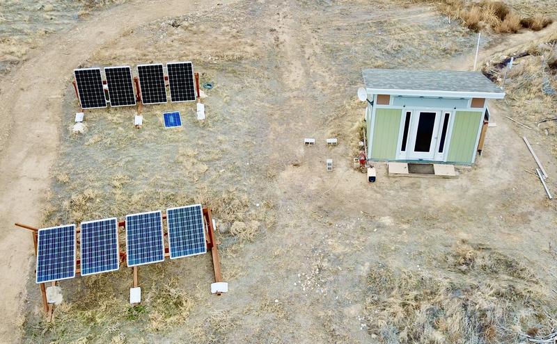
The first couple posts are about a big “A-frame” install over by my office. I’m not totally happy with the south facing panels out there, and I’m taking the opportunity to both rearrange panels to better suit my needs, and to work out details for the home install - which is far larger! It’s better to work out problems in a smaller scale before going big - and I’ve certainly decided to do some things differently as I scale up!
So, this week, I’m talking about the base for my new office solar - the footings and the frame!

This involves, as do most of my projects, an old tractor, some sketchy machinery, wood, paint, and more!
A-Frames? East-West Panels?
Why am I going about putting up solar panels on A-frames? Solar panels should point south, right?
If your only goal is maximum per-panel production, sure. Face the panels south, and if you’re going with a fixed mount, your latitude as an angle away from horizontal is probably the right ballpark to optimize annual production. But the problem with this is that south facing panels produce energy at solar noon - and they don’t produce much energy in the morning or evening.
With grid tie and net metering, this isn’t that big a problem - you can produce energy whenever, and use it whenever (as long as you ignore the grid impacts of doing this). But if net metering goes away (as it’s likely to), producing energy when it’s actually needed is an awful lot more valuable.
More importantly, for an off grid system (which my office is), waiting around for mid-day sun to recharge the batteries is just pointless. I threw a couple spare panels on my office wall as an experiment, and they’re online far earlier in the morning, recharging the battery bank long before the main array has even woken up in the summer!

Worse, the summer sun comes up and sets rather north of the east-west line, so my south facing panels are quite literally shading themselves for the first few hours of sun in the summer! It doesn’t matter that much, in that I still have more than enough sun for the day (and, yes, these panels are still at winter tilt, showing how much I actually need the power).

My plan here, for both the office and the house, is panels that face east and west. I’m putting them at a 45 degree angle, so they’ll catch morning and evening sun well, with a bit less production than I might otherwise have a mid-day. But - if this works as it should, I’ll have production for the office that gives me a very long solar day, and for the house, production that matches our demand far more closely!
It really doesn’t impact the system cost that much, especially for ground mount. You can over-panel the inverters pretty heavily, and panels got cheap recently!
Ground Mount: Easier!
Why am I going with ground mount instead of roof mount?
For my office, it’s simple - my roof slopes to the north and I need far more panel than my roof would support.
For the house, it’s a bit more complex, but I can get some backup power out of ground mount panels, get something far better suited to our consumption patterns, and can avoid some of the complexity of roof mount. Under NEC 2017, which I’m under, I need per-panel electronics to handle the (IMO, rather nonsensical) rapid shutdown requirements. I could use microinverters, but there are none around that will give me any sort of backup power (yes, I know about Enphase’s IQ8s - they’re still not for sale and I still haven’t found more than press releases on their actual capabilities). String inverters cover that, but I can’t use those on a roof system without per-panel electronics, and that negates the ability to get backup power out of the array.
Plus, it’s easier to clear snow off a ground mount.
I Am a Dwarf and I Dig in a Hole!
Diggy diggy hole, diggy diggy hole!
The starting point for ground mount is some sort of hole in the ground filled with cement, typically. I’ve gone without this for my office panel frames, which are still holding up fine, but I want something more permanent for the big arrays.
So, I’ll put a hole in the ground, fill it with concrete, and bolt the arrays to that!
I even have a tool for digging big holes fairly deep into the dirt. This is an old Ford 9N tractor with a post hole digger - which I’ve covered before. Tractor’s 80 years old, post hole digger is… a horrifying bit of machinery, and between the two, I can dig holes about three foot deep without too much effort unless I hit a big rock or hardpan.

The holes are defined by a couple scoops with a manual post hole digger - it provides a hole for the tip auger to screw into and generally positions the main auger decently enough for concrete work. I’m not half inch precise, but neither do I have to be.
I have to dig in neutral because of how the mechanisms work, so I just get the tractor positioned, shove a couple rocks under the wheels, and go at it. On level ground, at least, I can actually reposition the tractor manually by pulling on the top of the rear wheel - though anymore, I’m pretty good with the clutch on it.

Ideally, I can just dig and empty the auger until things are as far down as I can get. Realistically? It just depends on the rocks. Some holes I get lucky, some I don’t.

For my office, at least, I mostly got lucky. There were some rocks, but the dirt was mostly a sandy soil that wasn’t too bad to dig. I had to clear it out a few times with the manual post hole digger, and tidy up the holes, but the bulk of the digging was tractor and auger powered. Not bad for an 80 year old! Most of the holes ran down near three feet deep, which is well below the frost line.

Pouring the Footings
There’s plenty of information out there about pouring footings on the internet. I can’t promise mine is ideal, but it’s probably overkill enough to work most places. We live in a very dry climate, so I’m not that worried about frost heaves and such - but, still, I may as well make sure the footings are properly in place. I fully expect, in 100 years, after I’m dead, someone will be cursing my name when they try to rip these stupid things out and realize they just go down, and down, and down.
I’m using some concrete forms to help shape the protruding concrete, and also to help provide a slick surface for the earth to move against if it’s going to do crazy stuff like frost lensing and other “I want this out of me!” tricks that dirt does.

How does one transport a portable mixer a half mile or so? One could use a truck, or one could just put a wagon (“not for highway use”) on the back of a Ural and trailer it on the road. It’s fine out here.

Why, you might be inclined to ask, would one buy a smaller bag of concrete when there are 80lb bags cheaper per pound?
Because 80lb bags of concrete suck to work with, that’s why!

For this particular set of posts, I’m using a post base and a J-bolt that’s poured in place. The bolt is set in the concrete, and you screw the top on. It requires halfway accurate J-bolt positioning, which turns out to be harder than it seems.

I built a bunch of squares for supporting the forms. This lets me set and level the forms relative to each other, and then they stay put while I fill them with concrete. A screw through each side into the tube is sufficient to hold them as long as you’re not too violent with the tamping! These came after my first attempt to just use a pair of 2x4s - they don’t really do a great job of holding it stable. These are far better.

With these positioning squares, you can level and align the concrete pretty well before pouring. Screws go through the center of each side into the forms and hold them in place. Sit down with a level and, if needed, a long chunk of straight wood to get things leveled.
I generally don’t care about north/south level on this project - the frames will be slightly sloped south, and that’s perfect. I just want them level east to west.

Toss in rebar while pouring to improve strength. I’ve been told my footings are somewhat excessive - “Are you pouring house footings?” is a question I’ve received.

On these footings, I decided to use J-bolts and cast them in place. This is far, far more of a pain than it sounds like, especially if you need halfway accurate positioning and want the concrete well packed around them. It works, but I’ll be doing something different on the house system. You put the bolt in, pack around it, it shifts, then opens up a void, then it’s either too high or too low… really, just avoid this method.

Driving the Grounding Rods
One of the things I didn’t get quite right when I built my office was the grounding rods. I drove a single rod, most of the way into the ground, but it did hit a rock or something and rather stopped. I have a common ground between everything, but it doesn’t have additional grounding points out by the panels, and I’m just not happy with it. It works, but it could be more robust, and for the long term, I’d rather have good grounding rods driven. So I drove two.
If you’re not familiar with grounding rods, they’re very long hunks of metal designed to be driven rather violently into the ground. They’re metal, often have an outer copper coating to help with ground contact and corrosion and such, and are a pain to drive into the ground. They’re quite long, this one being 8’.

Years and years ago, I learned a lesson about ground rods. We had a bunch of wireless radios with lightning surge arrestors installed on a roof, and every thunderstorm, one or more of them would blow out a switch port on our main network switch. Even without an actual hit, the static buildup was enough to cause problems. This got old, fast, but I didn’t know how to fix it, so I just swapped cables around…
Eventually, a new installer showed up, and he was rather surprised to see a ground rod sticking out of the ground (that this whole set of radios was grounded to). After informing the other guy that ground rods are to be driven fully into the ground, they spent an hour driving it the rest of the way - and the problems stopped.
Drive your ground rods fully in. Like this!

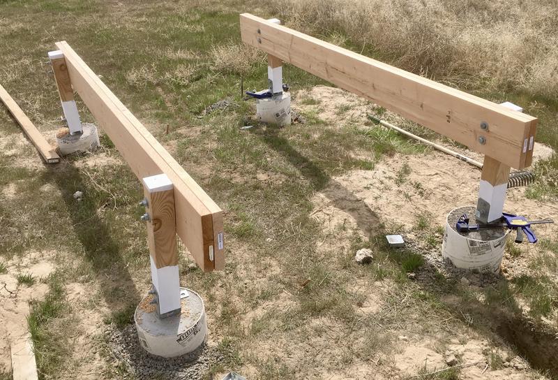
Installing the Railings
With the footings poured, the next step is the uprights. The base fits against the footing like this - there’s a nut and washer, then the big thick U for a 4x4.

These post bases fit a 4x4 - and there are several ways to secure a 4x4 to them. One could use a bunch of screws/nails, or one could drive some large bolts through halfway precise holes. I decided I liked the bolt idea, because they’re larger, stronger, won’t pull out, and clamp the post very firmly in the base.
My uprights are 2’ long, as a rough spitball for proper length and system height. I painted the ends before putting them in, in an attempt to better protect the wood, though I’m not sure it matters. Holes were bored on an old drill press, and I should have drilled the top holes as well, because I’m no good at getting the angles right freehand.

One of the perks of leaving the bottoms open (without the normal cap) is that I can adjust the bolts after getting everything positioned. I don’t have to have the positioning or angles perfect when putting the post holders in - I can put the uprights in, secure everything, build the frames, and then tighten down the base.
My concrete posts are somewhat high above the ground and there’s a large gap between the concrete and the base of the wood, so I’m not particularly worried about water causing problems. This is one of those “I live in a bone dry area” things that I can get away with and you might have trouble with somewhere wet. I’m also using Douglas Fir instead of pressure treated, because I prefer working with it, and, again, it just doesn’t matter for me.

Finally, some clamps, some drilling, and I had the side rails connected in place. This is where I learned, yet again, that I can’t eyeball the holes properly through 6” of wood. The bolts are seated, but not quite flat. For future projects, I’ll punch the holes on a drill press and then use that as a guide for the auger to put the holes through the rest of the wood. The side rails are a pair of 2x10s glued together with some construction adhesive.

But, the do bolt on, and the frames are ready to get painted and then get the As mounted on them!
Lessons Learned and Changes
Major things I’ll do differently for the house install:
- Pour the footings without J-bolts in them, drill and epoxy bolts in place.
- Bore holes in the top of the uprights on the drill press after properly working out their lengths.
- Use smaller bags of concrete instead of the 80lb bags.
But, they’re in, and my solar projects are actually under way.
Plans have been approved for the home solar, finally, and while I’ve not made nearly as good progress as I’d hoped on the house install this year (something about a pandemic and three weeks of people building a retaining wall out where I normally work), I should be able to get the home solar online by end of year, which is when it has to be done if I want to get grandfathered into net metering (which I absolutely do).
More updates to come in following posts!
Comments
Comments are handled on my Discourse forum - you'll need to create an account there to post comments.If you've found this post useful, insightful, or informative, why not support me on Ko-fi? And if you'd like to be notified of new posts (I post every two weeks), you can follow my blog via email! Of course, if you like RSS, I support that too.


