
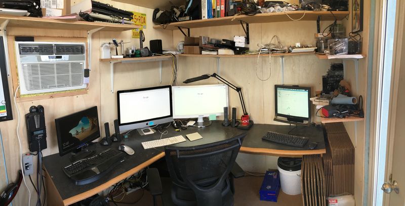
It’s been a little while since I’ve torn apart cheap bike lights out of China - but I’m back at it with this solar bike tail light! And, I’m tearing it apart in my solar powered workspace.

If you’d like one, they’re less than $3 on eBay right now.
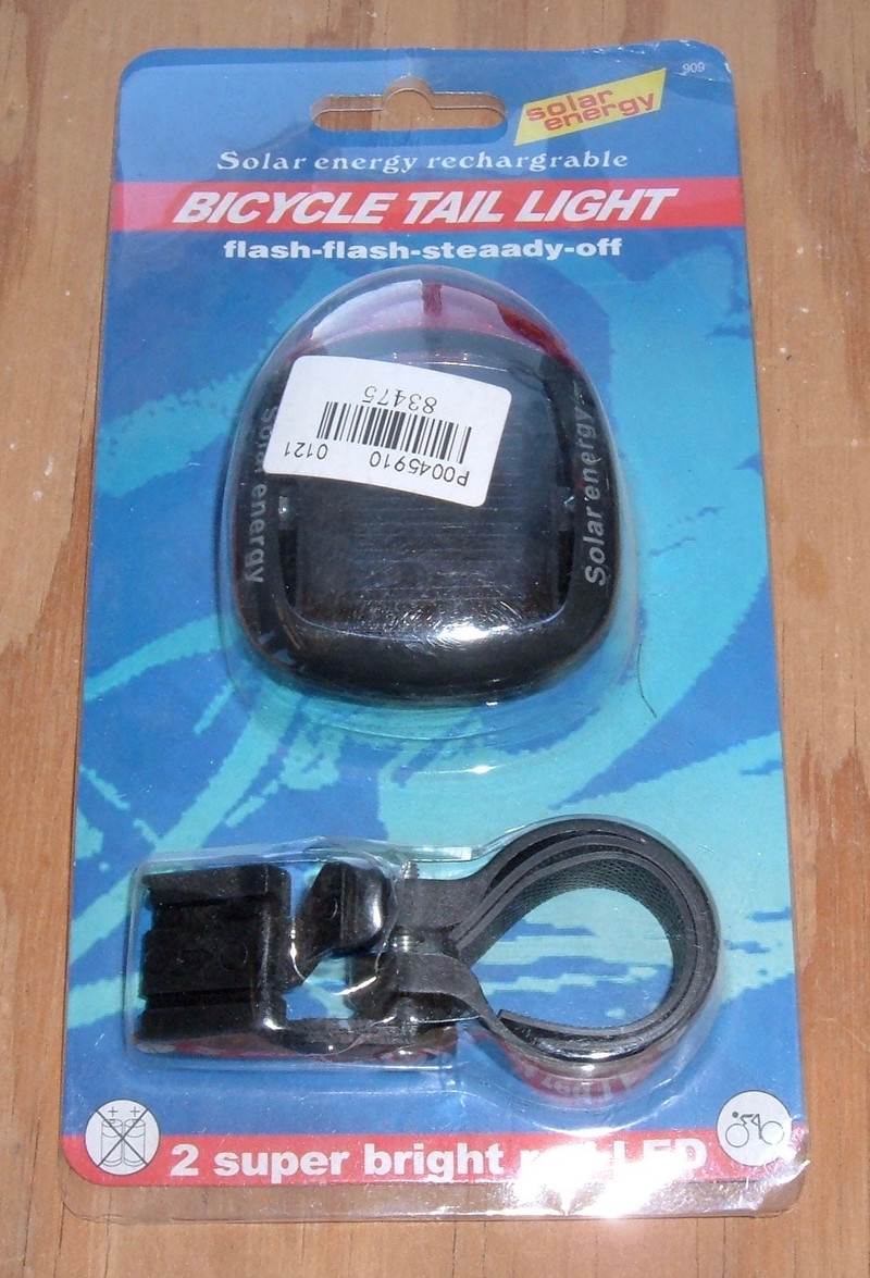
It’s powered by “Solar energy.”
It’s “solar energy rechargrable” - and it includes a “steaady” mode.
What’s in it? And is it any good? Keep reading to find out!
Why Tear Down Bike Lights?
I’m a fan of bike lights. I like having more light than I need on my bikes. There are a few ways to do this - cheap bike lights, or expensive bike lights. The expensive ones are nice, but some of the cheap ones are nice enough, and if I can buy, say, 10 of them for the cost of a nice one, I may very well be better off with a few cheap ones.
This isn’t the first bike light I’ve torn apart. I pulled apart a $5 Laser Light a while back, and I also did some analysis of a Cree “2000 Lumen” light early in the blog’s history.
Claims Made on the Box
The back of the box makes a few claims about this light - and I’m going to see if they hold up!
Specific claims I want to validate:
- Charge time: 2 hours.
- Run time: 4 hours in solid mode, more than 8 hours of flashing.
And, of course, I’m going to tear it apart and find out what all is in it.

Solar Energy Bike Light Overview
The top of the light has a very small solar panel under a clear plastic lens, and some nice printing on the side that lets everyone know your bike light uses “Solar energy.” Facing back is a nice red lens, with 2 LEDs inside.

The bottom has the bike mount bit (it works just fine and is therefore uninteresting) and the Button. This Button toggles between the four modes - a rapid flash (two flashes then a pause), a even on/off flash (50% duty cycle), steady on, and off (off, apparently, being counted as a “mode”).

Weight
I’ve known enough cyclists over the years to know that for many people, weight is huge. Or, rather, lack of weight. I can’t say I really care about that, mostly riding heavy electric bikes, but this is a really, really light light. Yes, I did that on purpose.
The entire assembly, with the mount, is 42 grams. Of that, the light unit is 30 grams, and the mount is 12 grams. For those who prefer the avoirdupois ounce, the whole unit is 1.5oz.
Initial Teardown
The underside of the bike light has two screws. Exposed screws are often a good start in the process of dismantling something, so they come out.
No glue! Excellent! Cheap gizmos are often glued together, and this one isn’t. With those two screws removed, the top cover pops right off. Underneath is the solar panel - and two more screws that I’ll remove as well.

After those two screws are out (four screws so far), the solar panel/LED module pulls out, leaving the bare case. The LEDs stick through those two holes into the lens.

If you look at the bottom part, you can see the tongue on the inside of the mating surface. This is useful for keeping water out. I wouldn’t say this is the best sealed thing I’ve ever seen (it has zero rubber or anything else), but I suspect it will work just fine on a normal bike in terms of keeping water out. The only potential problem would be the top plastic fogging or freezing up in a really humid climate, but I don’t have an easy way to test that.
I’ve had one of these on a bike of mine for a while, and I haven’t noticed any problems with moisture. I suspect it leaks enough air that even if water gets in, it can get out easily. Also, there’s plenty of space in the bottom for water to pool without hitting any of the electronics - so you’d pretty much have to go swimming with it to cause a problem. Excellent!
The Solar/LED Module
With the two screws securing the plastic solar module removed, the core module pulls right now. The most obvious thing about it is that the solar cells are firmly buried in about half a centimeter of epoxy or something - there’s a clear poured coating over them keeping them in place. It’s hard to photograph, sadly, but you can see the curving of the coating in the top left corner of this photo.
There are seven small panels, more or less lined up next to each other. I expect each one is a solar cell of 0.6V or so - but I’ll dive into that later.

Flipping it over, there’s a battery (comically undersized for the space it’s rattling around in), the copper side of a remarkably simple looking circuit board with a few wires soldered on, and the switch. The white glob hides a basic IC of some sort, and is likely responsible for the flashing (as nothing else visible here could be a flasher module).
The battery wires into the board are obvious, and there’s a metal ribbon snaking into the board from the top right corner of the plastic assembly, with what looks like another one peaking over the lower right corner. Those probably bring power from the panel!

The lone screw holding the board in comes out easily, and the board pops free. That metal strip in the lower left corner is short - this might make analysis a problem.

There is absolutely nothing fancy on the back of the board. There’s a diode and what, to my moderately untrained eye, appears to be a 12Ω 5% resistor.

The Battery
There’s a suspiciously green, bulgy object hooked up with what look suspiciously like battery wires - but it’s covered in plastic. That just won’t do!

Look! Button cells! Ni-MH, CE-something, ZMZ40H. Two, in series.

That’s some cute nickel strip. Tiny! And check out that solder job on the positive wire - someone got the wire a bit hot and burned the insulation. It’s always interesting looking at these hand soldered devices - there’s certainly variety.
The tabs are spot welded onto the batteries.

Now, what are these batteries?
They’re nickel metal hydride - that’s what NiMH means. And, as near as I can tell, H40 or 40H or such refers to 40mAh. So this is a 2S NiMH pack, 40mAh. That means a fully charged voltage of around 3V (1.5V/cell), with a low voltage of around 1.6V (0.8V/cell).
Will they actually provide that? I have no idea (I doubt it) - but I’m more interested in how they work in the whole assembly. I don’t really care what the battery is if the whole unit works as advertised.
Tearing Apart for Analysis
I want to do more analysis on this board, but I can’t - the wiring is too short, and those thin metal ribbons coming off the solar panel are too fragile.
So I tore it apart entirely and rebuilt it with 22 gauge solid core leads on all the terminals. These are about the perfect size for inserting into breadboards, which means I can reconfigure the device at will without having to solder and resolder to it!
The solder they used is utter crap, though. Seriously unfriendly to work with. Oh well. It holds, and I really can’t fault a unit that much for not being “dismantle me friendly.”
A soldering stand is really useful for tasks like this. The power leads to the board are attached.

The battery leads are already small enough to slide into a breadboard, so I just stripped and tinned them. Snip the slightly bulbous tip off, and it’s good as is. If you want to turn stranded wire into solid wire, a bit of solder works wonders!

Do that a few more time, and you get a collection of parts looking like this.
Coming off the board to the top, battery leads. To the right, solar panel leads. Yellow, because it’s the “sun input.” And coming off the solar panel, green - for “green energy.” Definitely symbolism, and not because those happened to be the color wires I had laying around.

The ribbons coming off the solar panel are still incredibly fragile, so I used hot glue to secure the whole mess together. Now I can work with the panel and not worry about the ribbons.

Breadboard Analysis
Why did I just spend all this time putting wires on the components?
So I can do this!

I’ve assembled the system on a breadboard, with a handy voltmeter/ammeter standing by. Showing, right now, that the battery is at 2.69V. I can reconfigure it as I want without having to pull out a soldering iron. This lets me test the solar panel in isolation, as well as testing the battery and LED module in isolation. I wouldn’t want my time tests affected by inadvertent charging!
With a bit of rewiring, I can monitor both the voltage and amperage coming off the battery and into the bulb. Right now, the system voltage (no solar attached) is 2.37V, and 19.9mA are flowing (plus or minus some tolerance for this little measuring unit).

Solar Panel and Charging Analysis
I can also test the solar panel in isolation and determine (in bright sun):
Voc (open circuit voltage): 4.15V, or 0.592V/segment
Isc (short circuit current): 32.5mA
It’s a small panel, but it’s most certainly a solar panel.

With afternoon sun through my office window, I discover that my voltmeter/ammeter doesn’t actually keep all the digits lit, and my camera is too fast with the bright light to capture it.
However, in the “sun through my window” mode of charging, the panel is putting out 7.3mA at 2.71V.

Outside, the panel is pushing 3.04V at 30mA into the system - nearly 0.1W! Having the plastic case cover reduces the current by about 3mA in most orientations.
The current flowing from the panel into the battery is the same, but the voltage is about 0.3V lower at the battery side than the panel side. Which, interestingly, is about the voltage drop over certain types of diodes…
Also, experimentation with a full battery indicates that while the resting voltage is around 2.86v, putting the unit in the sun brings this up to 3.12V or so, depending on how the panel is pointed. It doesn’t look like there’s any real charge regulation to speak of.

Solar Panel in the Shade
The solar panel sitting in the sun is all well and good - but that’s not where bike lights usually sit. They’re often under the seat, tucked up high. At least, that’s where mine live.
How does this panel do, with the plastic cover on, with purely indirect light?
Depending on the conditions, in the shade, it generates somewhere between about 0.5mA and 1.5mA - which is a whole lot less than the 25+mA it generates in the sun! This is a whole lot less charging current, but it’s actually quite good news for the battery!

At a steep slant, as the panel might see with evening sun coming under the seat, it charges at 4-8mA.
It won’t charge inside, though. Not enough photons.
Board Analysis
“All roads lead to the IC.”
With the sun behind the board, the simplicity of the layout becomes obvious. The front side also makes it obvious, but this side shows more components of interest (the diode and resistor).
Both negative terminals (solar panel and battery) are connected together at all times, as far as I can tell.
The solar panel positive (lower right, yellow wire) is connected via a diode to the battery positive (orange wire, center bottom). That explains the 0.3V drop - it’s likely a germanium diode of some variety that exists to let the solar panel charge the battery, while not letting the battery drain through the panel.
It’s not a bad setup, though it does manage to be entirely unregulated…
On the output side, the 12Ω resistor manages the current for the two LEDs connected in parallel. They’re switched on the ground side by the IC.

Battery Charging and Abuse
It’s interesting how this charging is regulated - which is to say, it’s not, far as I can tell. The solar cell can push 30mA of current into the battery any time it’s in direct sun - and about 1mA in the shade.
On what seems to be a 40mAh battery, charging at 30mA is an 0.75C charge rate - well in excess of what a safe sustained charge rate for NiMH is (you can charge them indefinitely at 0.1C, though some manufacturers don’t recommend this). That said, NiMH tolerates an overcharge fairly well, and just dumps the excess as heat - of which there isn’t much here (about 0.1W max, which those cells can easily dump, though it’s not good for them).
This is an example spec sheet for a small 40H NiMH cell, and I’ve gone through a number of spec sheets. They all agree that the batteries should really be charged around 4mA, and that they can stand 1-3mA of sustained overcharge. The spec sheet I linked refers to a fast charging mode of 20mA for 3h, time controlled. That one also says the cell is rated for a 4mA indefinite overcharge, with 8mA for up to a year.
Charging unregulated at 30mA is obviously well beyond that limit.
However, in shady conditions (say, tucked up under a bike seat), the charge current is much lower - in the range of 0.5-1.5mA! This is entirely within the suggested charge current for the battery, and with the tiny current draw of the device, it’s enough to keep things fairly full.
That low shaded panel charge current certainly won’t charge the batteries in two hours, as stated on the box. It will charge them over time. But, I have to admit, you can charge the batteries in 2 hours of direct sunlight. It doesn’t mean you should, but you can.
Testing and Experiments
The case claims it’ll last 4 hours in lighting mode. So, I charged it fully, tossed my meter in the loop, and ran it in “fully on” mode, logging with the highly sophisticated method of “Glance over at it every now and then, write down the voltage and amperage.” This is the result.
Before I started the test (-1 minutes in this chart), the battery was at 2.91V, dropping to 2.65V as soon as the LEDs came on.

It lasted almost exactly 2 hours. Not 4. The current drops off significantly as the voltage drops, which is to be expected - the 12Ω resistor handles the current limiting. These LEDs have a forward voltage drop of 1.8V-2V under normal operating conditions, so the resistor works with the remainder and controls the current - that’s why the current drops so much more rapidly than the voltage.
Starting out, the unit is pulling nearly 30mA from the battery. As it drains, the current drops lower and lower, with the LEDs getting visibly dimmer, down to about 4mA. Eventually, the voltage drops so low that the LEDs are just faint dim spots, and I terminated the test when they got to that point at 2 hours and 1.69v. There just wasn’t enough voltage left to drive the LEDs.
Mostly charged (about 2.6V and 28mA), the LEDs take 2.0V, the resistor is dropping 346mV (which works out with 12Ω), and the IC is taking the remaining 150mV. Further down the curve, at 2.18V and 17mA, the LEDs take 1.9V, the resistor is dropping 150mV, and the IC drops 110mV. Below about 1.8V, there’s just not enough left to drive the LEDs.
The light should last noticeably longer on the blink modes - 4 hours of 50% duty cycle sounds entirely doable, as does 8 hours on the more strobe-like cycle.
But it’s no 4 hours in lighting mode. Not the one I tested.
I ran the battery through my discharge meter at 100mA (the lowest I can test at), and it showed a whopping 9mAh of capacity. It certainly will produce more at the 10s of mA level, but it’s still not a very large battery. It might run for 4 hours with larger cells…

Charging in 2 hours, though? Absolutely. Even if I give the cells 40mAh capacity, the 30mAh the panel puts out will more than charge the battery in 2 hours. It’s really not good for battery longevity, but the panel will charge the battery in 2 hours.
Final Thoughts
This is an interesting little device. It’s a solar bike light, stripped down to the bare minimum. Everything there is required for basic functionality, and there’s no excess. It’s unregulated on the charge side, resistor regulated on the discharge side, and relies on the battery to take the abuse - which it seems to do, and is actually within what look like sane battery specs if the light is mounted as it commonly will be, out of the direct sunlight.
That said, it does work! It doesn’t meet the specs on the package (surprise), but it does actually meet the specs if you apply the standard Chinese spec correction factor of 50%. As far as charging goes, it meets that as stated.
It’s not fancy. I can’t say I expect it to last decades. But, if it does start lasting shorter than you’d prefer, just swap out the batteries. No glue involved.
The design is such that it’s no good if you let it sit in direct sunlight. A 25-30mA charge current will absolutely fry this size battery in short order. But, installed where it would normally be installed, the panel’s charge current is substantially lower and actually within the recommended range for similar batteries!
Is it deliberately designed this way or a happy accident? I really don’t know. That the panel is hand-poured, though, seems to suggest that someone might have thought this through, and marketing got their hands on the sunny data.
Should You Buy One?
I can’t tell you yes or no. Hopefully I’ve given you enough information to make a decision. I will say that I have one mounted on one of my bicycles and I’ll leave it there until it quits, at which point I’ll probably replace the batteries and reinstall it. Not having to think about charging or changing batteries is pretty handy, and it makes a great secondary light to have around.
Beyond that, it’s $3. Shipped. I wouldn’t recommend it as one’s only tail light, but as a “mount it and forget it” backup light that will always be there for you, at least for a few years, it’s pretty nice.
If you pick one of these up, how should you use it?
I very strongly suggest mounting it high under the bike seat. It’s going to get enough indirect light to charge, and this indirect light charging will help avoid damaging the battery. You really, really should not mount this anywhere it will get direct sun.
If you need to charge it quickly, set it in the sun for half an hour. But don’t leave it in the sun all day.
The current draw on the strobe mode is incredibly low, so it doesn’t take much to charge it back up. Even if the battery loses capacity over time, it’s still good for hours of nighttime use in the strobe mode, and it’s always going to be charging during daylight hours.
The spec sheet is not entirely accurate, but if you only let it see indirect sunlight, it won’t abuse the battery too badly, and you still do get multiple hours of light out of it. For $3!
Did you buy one? Do you already own one? Let me know your thoughts below in the comment section!
Comments
Comments are handled on my Discourse forum - you'll need to create an account there to post comments.If you've found this post useful, insightful, or informative, why not support me on Ko-fi? And if you'd like to be notified of new posts (I post every two weeks), you can follow my blog via email! Of course, if you like RSS, I support that too.

