

One part I find myself using somewhat regularly in projects is a lithium battery bank charger/USB power supply - it’s the guts of a battery bank phone charger, except always turned on. This provides a reliable 5V output for projects, charges from micro-USB if needed by the project, and offers some basic battery protection behaviors (on paper, they should turn off below a certain input voltage and stop charging over another voltage).
However, while fighting with the SparkFun ESP8266 WiFi Shield, I discovered that these units do not handle transients very well - if the load changes quickly, the voltage wanders around for a while before recovering. Different units behave differently, and I wanted to find out how different testers behave under this type of load - so I built myself a USB 5V Transient Tester!

Why? Because! I wanted something that did this, couldn’t find one easily available, and set out to build one. This is the sort of one-off bit of lab equipment that Arduinos are perfect for.
Interested? Read on!
Design Concept & Prototype
Before I went about building the full project, I played around a bit with a breadboard to see how the concept would work. Since I didn’t (at the time) have any power resistors, I built my own power resistor bank out of 150Ω resistors, because I had a bunch laying around.

The bank of three resistors in parallel works out to 50Ω - so on a 5V supply, 0.1A. The bank of 15 works out to 10Ω - or about 0.5A. I used some random MOSFETs I had laying around to switch them, and I toggled the resistance (and therefore current) to see if USB power supplies would sag enough to be of interest - and they most certainly do!

The basic requirement for something like this is to switch loads in and out rapidly to test behavior under rapidly changing demands. A bonus feature is that I can load up power supplies and see where they fall out of spec - either USB spec, or what I need for my hardware.
I’ve got a cheap DSO138 scope I intend to use for analysis of the transients, but I wanted my tester to be able to report voltage and current as well. This gives me the ability to ramp current until the voltage falls below a particular point, report out details, and generally make things more useful.
My design is resistor based instead of MOSFET load based. I considered both, but building a MOSFET based constant current load is another project for another day (and a better scope), and I wanted something built reasonably quickly.
I’m using a variety of resistors for the load, and switching with some of my standard NPN MOSFETs I keep around for switching purposes. To switch things instantly (or nearly enough so), I’ve got a shift register controlling the outputs. It would have been easy enough to control the Arduino ports directly, but I’ve got a fancy LCD and button shield on top, and that straddles multiple ports. And I had these shift registers laying around…
In order to keep things reasonably simple, I picked a set of 8 resistors to use. Since the devices under test should be producing 5V, the amperages are calculated around a nominal 5V.
- 2x 5Ω resistors @ 1A
- 1x 10Ω resistor @ 0.5A
- 2x 25Ω resistors @ 0.2A
- 3x 100Ω resistors @ 0.05A
With this set, I can select any current between 0.05A to 3.05A in 0.05A steps (actual amperage depending on the voltage being produced, but I’m mostly interested in transients, not load testing).
I’m using a pair of 1% 0.1Ω resistors in parallel for current sensing, for a total shunt resistance of 0.05Ω (or about 0.15V across them at full rated current of 3A).
Making Things Fit
I ordered a few resistors for this project, but it’s pretty much built out of things I have laying around my parts bins. The prototype shield is something I have a lot of, and the prototype board is as well. The MOSFETs are parts bin, the shift register is parts bin, and at least some of the resistors are parts bin.
But the first step is to figure out how, exactly, to fit everything. This took a while and involve playing around with a bunch of different layouts

This is the layout I finally settled on - a bank of 8 MOSFETs across the back, the load resistors across the center, and the shunt in the corner.
I’m aware that the cooling here isn’t amazing, but remember - this isn’t a load tester. It’s a transient tester. I have a perfectly good USB load tester with a heatsink and fan that I’ll use for straight up load testing.

The back of the prototype board is pretty standard - rails for voltage and ground, bridges to couple parts together, all on a 0.1” grid.
I’m using the bottom rail here as the current feed into the measurement shunt - it will float slightly above the ground voltage at high currents, but should be fine.

I didn’t really trust the copper here to carry 3+A without much of a voltage drop - but this is a trivially solved problem! Just add solder to the copper after coating it with flux, and you can carry as much current as you want (within some decently large values of want). I’m not sure what the total resistance across here is, but it’s very low now.

A bunch more time soldering, and the board is done! You’ll note the MOSFETs are alternated back and forth - this is to avoid the backs from making contact, as they need to be isolated from each other. The back plate is connected to the drain terminal (center terminal, where the resistors connect), and if they touch, it’d be adding other resistors into the mix incorrectly.

The underside is just more solder bridging. It’s not the prettiest thing I’ve ever soldered up, but it works out electrically and shouldn’t have any trouble with a few amps.

Finally, I figured out how to mount the resistor board to the Arduino shield - a row of header pins does the trick and is easy enough to solder to both.

Control Wiring & Voltage/Current Measurement
Since the control is being done with a shift register, I need to wire up the shift register to control the MOSFETs. I’ve got this great little Arduino shield I’m mounting stuff to - may as well use it!
The top of the shield has both the shift register and my voltmeter on it. The shift register is used to control the MOSFETs, and the voltmeter is used to monitor both the power supply voltage as well as the voltage across my shunt (giving me the amperage). It’s an ADS1115 unit, which supports variable gain - I can use the full range for measuring the 5V USB voltage, then up the gain for measuring the 0.1V or so across the shunt resistor.
It supports differential measurements, which is a bit more accurate for something like this as well.

The underside has the connection wiring (though the voltmeter doesn’t have sense lines coming off yet). Power and ground are wired, some of the pins are tied to Vcc or ground (if I don’t need them), and the control signals are routed. I try to avoid using D0 and D1 unless I have to, as I do like my serial output. The voltmeter is wired to the I2C ports, as it talks over I2C.
Doing this is kind of like routing traces on a circuit board, but a bit more hands on and chaotic - also, a bit more 3D. You can have lines running over lines and connections, as long as you don’t melt the insulation.

With the control lines run out to toggle the MOSFETs, the actual control side of things is pretty much done!

I still need to run the voltage sense lines over, but this is about what things are going to look like.

Power Wiring
Running power from a USB power supply requires a USB connector!
It turns out I don’t have much wire between about 20 gauge and about 14 gauge. So I used the 14 gauge wire for hooking up the USB-A connector to my gizmo. I have a bunch of these ends laying around and build a lot of my own power cables at this point, so it’s nothing new, though perhaps a bit overkill.

The other ends are then soldered to the system. The negative side goes to the “real ground” on the far end of the current sense shunt, and the positive side goes to the positive rail.
This also means that my MOSFET negative rail will be floating slightly above 0V, and I’ll be driving the MOSFETs slightly negative when shutting them off. This is not a problem at all.

Well, it certainly looks hand-built…

Finally, the voltage sense wires are soldered in place. I’m using differential sensing (as opposed to single ended sensing) because the accuracy is a bit better for things like this, and I don’t need four voltage inputs.

Removing Barrel Plugs
You know what? I hate the stupid barrel plugs on the Arduinos. I’ve never used one, and all they do is prevent some custom shields from sitting properly.

Fortunately, I have a solder sucker, desoldering braid, and a bit of time to make my life easier.
Really, I suggest you do this. It makes shields fit so much better, and who really uses those stupid barrel plugs anyway? All my barrel plugs seem to end up putting out 5V.

Display & Controls
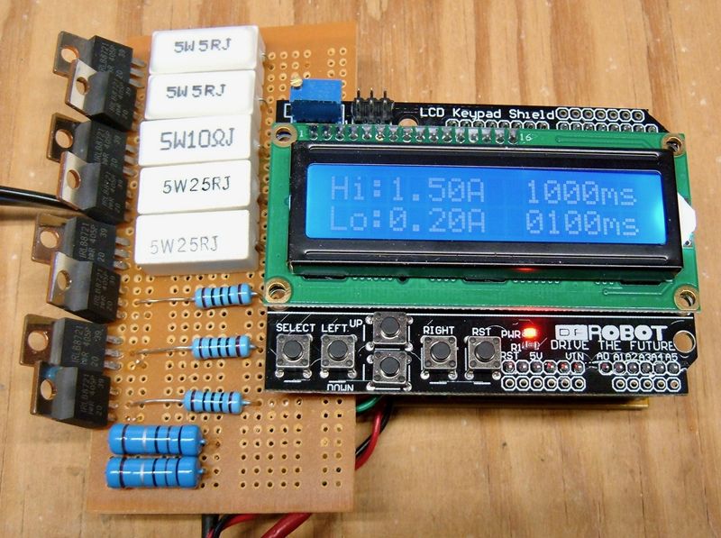
Finally, with the control shield and resistor bank attached, I can stick a display on top. This one is annoyingly hard to photograph…
This display shield also has a set of buttons attached. A standard diamond arrow set, a select button, and a reset button!
This is a DFRobot LCD Keypad Shield - there are a variety of shields along these lines, and they generally work the same. There’s a standard LCD with a bunch of voltage dividers on the buttons that feed into the A0 pin - check the voltage, you can get a pretty good idea as to which button is pressed. It’s kind of a neat little hack.

Random Bits of Testing
At this point, I sat down to do some testing. I wanted to ensure everything was working as hoped.
The first thing I tested was the switching speed of the shift register to MOSFET linkage. It’s important to switch loads reasonably quickly.
This trace is at 50us per division. I’m good! It’s nearly instant at this resolution, and I can’t get the triggering to work quite right at faster intervals, but I see no issues with “nanosecond level switching” for testing USB power supplies.

The second thing I tested was the 5V output of my Arduino shield. I’d been testing the voltmeter against the Arduino 5V and 3.3V rails - and my 5V rail is really, really low.
I’m not sure what’s going on here. There’s a significant voltage drop through the USB switching transistor, as far as I can tell - it might be related to me removing the barrel plug, but I’m not sure. I’ll investigate more later.
In any case, I switched over to one of my cheap Chinese clones (that I’d also removed the barrel plug from), discovered that the CH serial driver kernel panics OS X 10.12, updated that, and went on my way with a 5V rail resembling 5V.

Software
The software is a bit interesting, because I decided to write up something reasonably complex for configuring the board. I can move a cursor around with the arrow buttons, change values within a limited set of ranges, and it saves the settings to EEPROM so I have them next time I power up.
Not having written something like that before, and not wanting to write a ton of weird special cases, I came up with a few data structures that make my life easier and make the code simpler. It works really, really well, and is slick enough that I’m going to do another post on it for those curious.
Once the values are configured, runtime is pretty simple - toggle between the high and low load states (you could reverse them - the software doesn’t care), report the voltages and amperages, and do that until told to stop.
While doing that, I can hook up my scope and do some analysis!

You can see the drop on one of my battery packs - and around 0.05V (1%) ripple when under load. This is an old pack that’s seen a lot of use, but as far as I can tell things are still entirely within USB spec - which is to say, USB spec doesn’t say much about ripple, so you could have half a volt bouncing between min and max allowable voltages and be compliant - and why I’m interested in testing the supplies! There’s about 0.5V between the highest and lowest voltage seen during the transients, which is 10% of the voltage, and therefore worth paying attention to.

With the test program running, the LCD shows the low and high voltages and amperages (as measured across the device). This is mostly for sanity checking purposes, but I have the data - I may as well display it!

So, that’s it for this build!
Parts List
If you’re interested, here’s a list of most of the parts I used. They’re all eBay sources, since I don’t really care when I get my parts, as long as they show up eventually. I have no problems waiting a few weeks for parts if they’re shipping out of China (also, I have a lot of parts bins, so I just order a lot and keep the spares around).
1x Arduino (CH serial, micro USB power)
1x Prototype Board (5cm x 10 cm)
And a bunch of wire.
Comments
Comments are handled on my Discourse forum - you'll need to create an account there to post comments.If you've found this post useful, insightful, or informative, why not support me on Ko-fi? And if you'd like to be notified of new posts (I post every two weeks), you can follow my blog via email! Of course, if you like RSS, I support that too.


