
Last week, I posted about a little transient tester I built for analyzing USB power supplies and battery packs. I wrote what I consider to be a reasonably interesting little button based menu for setting values and running tests. It supports setting current and time for two stages of operation (high and low current) with a set of 4 buttons, running tests and reporting data, and does this with quite a small memory footprint. It also supports setting the current by the 0.05A steps that the hardware supports.

It also shows off some techniques that I feel are quite appropriate for any sort of embedded programming - bit packed structs, hard coding some of the screen attributes (only two rows), etc.
So, come on along for the journey!
Transient Testing
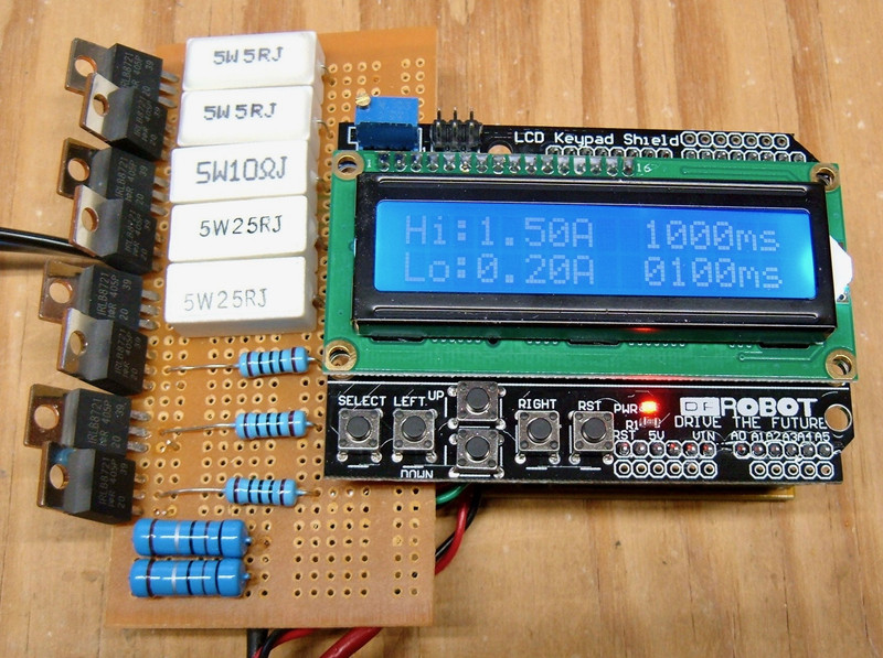
I built myself a little gizmo for rapidly switching loads on USB power supplies. This is useful to be able to better understand how various options for 5V power handle rapid load changes, as might be the case with an Arduino and a wireless card that rapidly wakes from sleep and draws power to transmit.
I built my tester with a bunch of power resistors, a bunch of switching transistors, and a 16x2 LCD screen with a few useful buttons (arrows and select). With the tester working, it was time to write the code for the display and actual useful operation - so I did.
The code is what I consider “reasonable code for an embedded system.” I use tricks to save memory when reasonable, design for my environment, and end up with some pretty tight code. All told, this is the result:
Sketch uses 7,690 bytes (23%) of program storage space. Maximum is 32,256 bytes.
Global variables use 327 bytes (15%) of dynamic memory, leaving 1,721 bytes for local variables. Maximum is 2,048 bytes.
Could I do a bit better? Probably. But I’m not going to complain! This comfortably fits my environment, leaves room for future expansion, and I’m not going to overflow my stack any time soon.
Menu Operation
The menu is pretty simple - you set the Hi and Lo desired current in amps, and then how long (in ms) you want each mode to operate. It toggles back and forth between these states until told to stop.
The left and right buttons move the cursor, up and down set the value, and going off the end of one row puts you at the beginning of the next row. The only places the cursor stops are the actual digits - it skips over the letters and spaces.

The Code
You can find the full source file here: https://github.com/Syonyk/USBTransientTester/blob/master/USB_Transient_Tester.ino
I’m going to focus on the bits that are interesting and explain what I was doing with them. You can grab the full file above, but that’s probably not useful unless you’ve built a clone of what I’m doing!
Global Variables & Defines
Embedded programming is a bit weird in that often, global variables are used, and make sense to use. Things like the interfaces to your hardware will always need to be active and accessed across the code, and there’s no point in passing pointers around on the stack for something that exists for the entire operation of the code - or for data elements that are used multiple places. If they are going to exist for the full duration of operation anyway, you make things a bit more efficient by making them global.
Since I knew I wasn’t going to be tight on memory for this project, I instantiated several global variables and structures directly in data memory. For a project that’s tight on memory, or a library, you absolutely should not use more global memory than absolutely required. For this? Well… I probably could have moved some of this to program memory, but I didn’t need to.
// Initialize the DF Robot display with the proper pins.
// This is using the stock LiquidCrystal library - no I2C support needed!
LiquidCrystal lcd(8, 9, 4, 5, 6, 7);

Adafruit_ADS1115 ads;

// Current, in 0.05A steps, per shift register output pin.
// 20 - 1A - 5Ω resistors.  Etc.
const uint8_t current_per_pin[8] = {20, 20, 10, 5, 5, 1, 1, 1};

/**
 * Store the digits of the current and time.  This is the "display
 * representation" that is converted for actual use on test start.
 */
uint8_t amps[2][3];
uint8_t time[2][4];
Defines are useful for constants - they’re evaluated at compile time and don’t take up memory like a const variable would. They’re great for things like “which hardware ports are attached to which functions” and the like, as well as constants for decoding button presses.
// Shift register clock, data, and latch pins.  All digital IO pins.
#define SR_CLOCK 2
#define SR_DATA 11
#define SR_LATCH 3

// https://www.dfrobot.com/wiki/index.php/LCD_KeyPad_Shield_For_Arduino_SKU:_DFR0009
#define btnRIGHT  0
#define btnUP     1
#define btnDOWN   2
#define btnLEFT   3
#define btnSELECT 4
#define btnNONE   5

// How long after a button press to delay for debounce and scroll.
#define BUTTON_DELAY_MS 200
Display Update Structures and Arrays
The core of my display update process is in the (bit packed) structures and the arrays that drive the “button press update routine.”
I rely on the fact that my upper and lower rows are identical other than the text - the current row is used as an index into the value storage arrays for Hi/Lo current and time.
The code keeps track of the current cursor position, and uses this array of structures to update either the cursor position or the values based on the current location (and which key is pressed). You’ll notice that I’m bit packing the structures - all 7 fields are contained in 2 bytes, which saves a good bit of memory. Bit packing is very useful for embedded programming with a small range of values (as is the case here).
/**
 * A bit-packed struct for the cursor position updates.  This is the core of
 * the menu configuration.  It relies on the fact that the upper and lower rows
 * are identical except for some text.
 *
 * left_col and right_col are the corresponding columns to move the cursor to on
 * left and right button presses.  This adjusts the cursor position to the new
 * column directly.
 *
 * left_toggle_row and right_toggle_row indicate if the row should be toggled on
 * a left or right press - this handles row wrapping as you move off the end of
 * one row or another as there are only two rows.
 *
 * is_amps/amps_pos indicate if the positions are for amps, and indicate the
 * decimal position in amps.  Same for ms.  These are used to update the proper
 * decimal position in the array.
 */
typedef struct {
    // Column to move to on left key.
    uint8_t left_col : 4;
    // Column to move to on right key.
    uint8_t right_col : 4;
    // Toggle row on left/right.
    uint8_t left_toggle_row : 1;
    uint8_t right_toggle_row : 1;
    uint8_t is_amps : 1;
    uint8_t amps_pos : 2;
    uint8_t is_ms : 1;
    uint8_t ms_pos : 2;
} cursor_update;


// Populate an array of the above structs with the needed information.
const cursor_update cursor_positions[16] = {
    //  L   R  LT RT IA AP IM MP
    { 0,  0, 0, 0, 0, 0, 0, 0}, // 0  "H"
    { 0,  0, 0, 0, 0, 0, 0, 0}, // 1  "i"
    { 0,  0, 0, 0, 0, 0, 0, 0}, // 2  ":"
    {13,  5, 1, 0, 1, 0, 0, 0}, // 3  1s of amps
    { 0,  0, 0, 0, 0, 0, 0, 0}, // 4  "."
    { 3,  6, 0, 0, 1, 1, 0, 0}, // 5  tenths of amps
    { 5, 10, 0, 0, 1, 2, 0, 0}, // 6  hundredths of amps
    { 0,  0, 0, 0, 0, 0, 0, 0}, // 7  "A"
    { 0,  0, 0, 0, 0, 0, 0, 0}, // 8  " "
    { 0,  0, 0, 0, 0, 0, 0, 0}, // 9  " "
    { 6, 11, 0, 0, 0, 0, 1, 0}, // 10 1000s of ms
    {10, 12, 0, 0, 0, 0, 1, 1}, // 11 100s of ms
    {11, 13, 0, 0, 0, 0, 1, 2}, // 12 10s of ms
    {12,  3, 0, 1, 0, 0, 1, 3}, // 13 1s of ms
    { 0,  0, 0, 0, 0, 0, 0, 0}, // 14 "m"
    { 0,  0, 0, 0, 0, 0, 0, 0}, // 15 "s"
};
Handling updating the amps field requires a bit of fiddling, because the granularity of operation is 0.05A - that’s the minimum the hardware supports as a step. The hardware also only supports up to 3A - it can’t handle, say, 9A. So I needed to encode the max in the fields as well. For a lab tool, I’d rather make it as bulletproof as possible for later use.
This array of structures handles both of these needs for the amps field - increment amount and maximum value of the field.
/**
 * For updating amps, they can only be updated 0.05A at a time.  This structure
 * and associated array handles this - it sets the max value for each position
 * and the increment value for each position.
 *
 * Note that with the bit packing, each element is only a single byte.
 */
typedef struct {
    // Max value for this position.
    uint8_t max : 4;
    // How much to increment by.
    uint8_t increment : 3;
} amps_digits;

const amps_digits amps_positions[3] = {
    {3, 1},
    {10, 1},
    {10, 5}
};
The cursor is another case of bit packing for space efficiency, because I don’t need to support anything beyond what my hardware handles. There are two possible row values (0 and 1), which only needs 1 bit. The column values can range from 0-15, which can be stored in 4 bits. So there’s no need to waste memory space with a larger than needed data field.
Also, I handle toggling the cursor row as one goes off the end of a row by just adding one to the row value - it overflows back to 0, and properly alternates rows. This is one of those cases where knowing the exact hardware configuration makes it easy to optimize things tightly. It’s not “general purpose,” but it is well suited to an embedded environment where the hardware is constrained, and the software needs to work with exactly one variety of hardware.
/**
 * One byte of cursor information.  Row is 0-1, col is 0-15, on is binary, and
 * update indicates if the cursor needs to be updated on the next refresh.  Only
 * updating if needed avoids flicker of the cursor during normal operation.
 */
struct {
    uint8_t row : 1;
    uint8_t col : 4;
    uint8_t on : 1;
    uint8_t update : 1;
} cursor;
I’m skipping past some of the setup code - it’s just basic initialization.
Writing to the Shift Register
One reason I’m using a shift register is to allow for instant updating of the set of resistors enabled - a shift register lets you shift data in with a clock signal, then will update all the outputs at once. It’s a bit of an overkill way of handling this, but, hey. I like overkill.
This code sets the 8 output bits based on the global current-per-pin array, then shifts the data out to the shift register using some built in functions and latches the data, which updates the pins.
/**
 * Set the current to some multiple of 0.05A nominal.
 *
 * 0 - 0A.
 * 1 - 0.05A
 * 60 - 3A.
 *
 * You get the idea.
 *
 * This simply checks to see if the remaining amps requested are greater than
 * each pin's value, and if so, sets it.
 *
 * It does not rotate current around resistors.  This might be nice to do at
 * some point.
 *
 * Returns true if set properly, false if unable to set.
 */
bool set_current(uint8_t factor) {
    uint8_t output_value = 0;

    for (uint8_t i = 0; i < 8; i++) {
        if (factor >= current_per_pin[i]) {
            output_value |= 1 << i;
            factor -= current_per_pin[i];
        }
    }

    // Prepare the latch to take new data.
    digitalWrite(SR_LATCH, LOW);
    // Shift out the value.
    shiftOut(SR_DATA, SR_CLOCK, MSBFIRST, output_value);
    // Latch the new value and update things.
    digitalWrite(SR_LATCH, HIGH);

    // If any data is left, something went wrong.
    if (factor) {
        return false;
    }

    return true;
}
Reading Volts and Amps
I don’t technically need to read the voltage and amperage (I could use external hardware to do that), but I wanted an excuse to play with a voltmeter, so I play with one! This voltmeter has adjustable gain, so I set the gain, read the differential value (differential readings are a bit more accurate than single ended readings against ground), and do the math based on the datasheet and my shunt resistors to return the value. Note that I am using floating point here - it’s not generally a good idea for Arduinos, but it makes my life a bit easier and the time to read the voltage dominates the time of these functions.
/*
 * Configure the voltmeter to the proper gain, read the differential voltage,
 * and report back the desired values.
 *
 * Constants are from the ADS documentation for various gains.  get_usb_volts
 * returns the voltage across the USB port, and get_usb_amps returns the amps
 * across the shunt resistors (divides by the 0.05Ω value before returning).
 *
 * These are not particularly efficient functions as they use floating point.
 */
float get_usb_volts() {
    ads.setGain(GAIN_TWOTHIRDS);
    int16_t results = ads.readADC_Differential_2_3();
    return (0.0001875F * results);
}

float get_usb_amps() {
    ads.setGain(GAIN_SIXTEEN);
    int16_t results = ads.readADC_Differential_0_1();
    return (0.000007812F * results) / 0.05F;
}
Running the Menu
I’ve skipped over some functions related to reading buttons (just the reference code), updating the cursor (set it to the state and position in the global structure), and printing out some values (set the location, print values).
The next interesting function is the menu loop. This consists of reading the buttons, updating state based on the button presses (using the arrays set up previously), and sanity checking the values to ensure they don’t exceed the max allowed. When the “select” button is pressed, this simply returns to the calling code (the main loop then calls the test function).
I also update the cursor state here based on the millis() timer.
/**
   Runs the menu.  Format:
   Hi:0.00A  0000ms
   Lo:0.00A  0000ms
 */
void run_menu() {
    // Display the static characters.
    print_menu_initial();

    // Print the initial amps values.
    print_amps(false, amps[0]);
    print_amps(true, amps[1]);

    print_ms(false, time[0]);
    print_ms(true, time[1]);

    // Set things initially to amps-hi.
    cursor.row = 0;
    cursor.col = 3;
    cursor.on = 0;
    cursor.update = 1;

    while (1) {
        // Check for keys and update things.
        switch (read_LCD_buttons()) {
            case btnRIGHT:
                // 1 bit value - just wraps around on overflow.
                cursor.row = cursor.row +
                        cursor_positions[cursor.col].right_toggle_row;
                // Column is the absolute new value.
                cursor.col = cursor_positions[cursor.col].right_col;
                cursor.update = 1;
                delay(BUTTON_DELAY_MS);
                break;
            case btnLEFT:
                cursor.row = cursor.row +
                        cursor_positions[cursor.col].left_toggle_row;
                cursor.col = cursor_positions[cursor.col].left_col;
                cursor.update = 1;
                delay(BUTTON_DELAY_MS);
                break;

            case btnUP:
                // Increment the proper value.
                if (cursor_positions[cursor.col].is_amps) {
                    uint8_t pos = cursor_positions[cursor.col].amps_pos;
                    amps[cursor.row][pos] += amps_positions[pos].increment;
                    // If the value has overflowed, reset it to 0.
                    if (amps[cursor.row][pos] >= amps_positions[pos].max) {
                        amps[cursor.row][pos] = 0;
                    }
                    // Update the displayed value.
                    print_amps(cursor.row, amps[cursor.row]);
                } else if (cursor_positions[cursor.col].is_ms) {
                    uint8_t pos = cursor_positions[cursor.col].ms_pos;
                    time[cursor.row][pos]++;
                    if (time[cursor.row][pos] >= 10) {
                        time[cursor.row][pos] = 0;
                    }
                    print_ms(cursor.row, time[cursor.row]);
                }
                delay(BUTTON_DELAY_MS);
                break;
            case btnDOWN:
                if (cursor_positions[cursor.col].is_amps) {
                    uint8_t pos = cursor_positions[cursor.col].amps_pos;
                    // Since these are unsigned, increase to max if 0 before
                    // subtracting the proper increment value.
                    if (amps[cursor.row][pos] == 0) {
                        amps[cursor.row][pos] = amps_positions[pos].max;
                    }
                    amps[cursor.row][pos] -= amps_positions[pos].increment;
                    print_amps(cursor.row, amps[cursor.row]);
                } else if (cursor_positions[cursor.col].is_ms) {
                    uint8_t pos = cursor_positions[cursor.col].ms_pos;
                    if (time[cursor.row][pos] == 0) {
                        time[cursor.row][pos] = 10;
                    }
                    time[cursor.row][pos]--;
                    print_ms(cursor.row, time[cursor.row]);
                }
                delay(BUTTON_DELAY_MS);
                break;
            case btnSELECT:
                // Time to run - go back to the loop and we'll run it.
                delay(BUTTON_DELAY_MS);
                return;
                break;
            case btnNONE:
            default:
                break;
        }

        // The compiler should optimize this - is there any reason to use a
        // power of 2?  No, but it feels right.
        if ((millis() % 2048) > 1024) {
            // Turn it on if it's not on.
            if (!cursor.on) {
                cursor.on = 1;
                cursor.update = 1;
            }
        } else {
            // Turn it off if not off.
            if (cursor.on) {
                cursor.on = 0;
                cursor.update = 1;
            }
        }

        update_cursor();
    }
}
Running the Test
The test is pretty simple - it converts the values from the arrays into what’s useful for actually toggling states, and then loops between the “Hi” and “Lo” states, staying in each one for the specified time.
This also records the voltages and amperages in each state and displays them on the screen.
If the “select” button is pressed at any point, the exit request is latched and the code exits at the end of the loop. I could just reset the current and exit immediately, but this method uses the timing loops as a form of debouncing so that a press is only registered once.
void run_test() {
    uint8_t steps_hi, steps_lo;
    uint16_t time_hi, time_lo;

    // Storage for amps & volts.
    float amps_hi = 0, amps_lo = 0;
    float volts_hi = 0, volts_lo = 0;

    // Timeout, in millis.
    unsigned long timeout;

    bool exit = false;

    // Step 1: Convert from desired actual amp values to the offset steps.
    steps_hi = convert_amp_array_to_steps(amps[0]);
    steps_lo = convert_amp_array_to_steps(amps[1]);

    // Same for time.
    time_hi = convert_time_array(time[0]);
    time_lo = convert_time_array(time[1]);

    // Clear the screen and print the runtime header.
    lcd.clear();
    print_run_initial();

    /**
     * The voltages and currents are taken while running in the given state
     * (high or low), and are updated at the beginning of the following step.
     *
     * This allows them to stabilize out so the actual report data is transient
     * free.  The scope will capture the transients.
     */
    while (1) {
        // First: Set high current and calculate the timeout.
        set_current(steps_hi);

        timeout = millis() + time_hi;
        print_currents(1, amps_lo, volts_lo);

        while (millis() < timeout) {
            amps_hi = get_usb_amps();
            volts_hi = get_usb_volts();
            // If an exit is requested, set the flag for that.
            if (read_LCD_buttons() == btnSELECT) {
                exit = true;
            }
        }

        // Great - set the low current.
        set_current(steps_lo);
        timeout = millis() + time_lo;
        print_currents(0, amps_hi, volts_hi);
        while (millis() < timeout) {
            amps_lo = get_usb_amps();
            volts_lo = get_usb_volts();
            if (read_LCD_buttons() == btnSELECT) {
                exit = true;
            }
        }

        if (exit) {
            // Set the current to 0 before exiting to avoid cooking resistors.
            set_current(0);
            return;
        }
    }
}
Main Event Loop
The main loop is really, really simple. Run the menu, then run the test, then repeat! It will keep doing that as long as power is applied.
// The state just toggles between the menu and the test!
void loop() {
    run_menu();
    run_test();
}
Final Thoughts
Hopefully this is somewhat helpful in terms of seeing a more complex implementation than most sample projects. It drives an LCD for menu configuration based on buttons, runs some tests with data reporting, and, hopefully, isn’t absurdly complex in the process!
It shows off some techniques that I think are particularly useful for embedded programming as well - bit packing, designing for your specific hardware, etc. And, in the end, I have a very useful little tester that I’ll be using more in future blog posts!
Comments
Comments are handled on my Discourse forum - you'll need to create an account there to post comments.If you've found this post useful, insightful, or informative, why not support me on Ko-fi? And if you'd like to be notified of new posts (I post every two weeks), you can follow my blog via email! Of course, if you like RSS, I support that too.


