
Rebuilding the Pack for the iZip Ultra
The actual pack rebuild process went smoothly at first, then took forever while I repaired the welder, then smoothly again after I got the welder repaired.
I started with 50 Samsung ICR18650-32A batteries and a lot of parts, and ended up with a new battery pack!
Continue for an awful lot of photos of rebuilding a battery pack.
Spacers/Battery Holders
The first step in putting the pack together is to reconnect the battery holders & spacers I’d split when taking the pack apart. I used some gel type superglue to manage this. It took a bit of time holding things together for them to stick, but they did, quite well! The pack is also held together by the battery stripping and the tape, so this didn’t need to be incredible, just enough to hold things together for the build. This worked perfectly - you can see the rebuilt holder above the pack.

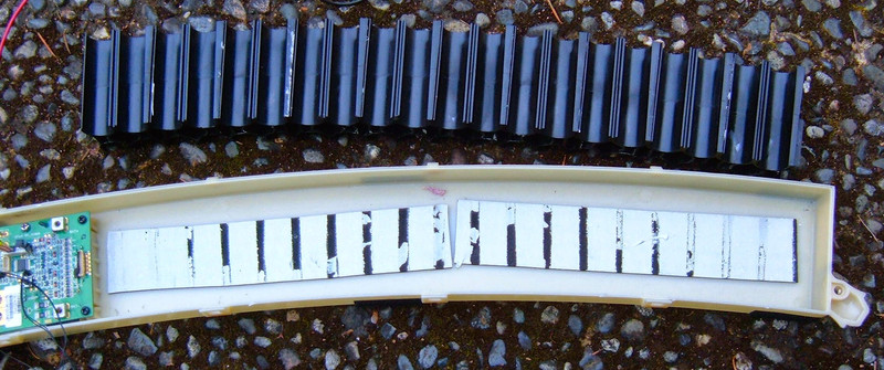
Positive Terminal
The positive and negative terminals of the pack are initially nickel strip, which is soldered to the main leads. I replicated this, and then heat shrink wrapped the terminal. Resistance is suitably low, and this isn’t exactly a high amperage pack to begin with. This is how the existing pack handled it, so I feel confident in doing the same thing.


First Battery Cells
I put the first 5 batteries in, cut some strip to length, and tacked them in place. This is easy! I’m using 10mm strip for the main parallels, with 8mm strip for the “X” to the center cell (and to connect the two side strips). This replicates the conductivity of the stock plating, more or less, and should be entirely fine for this pack - it’s really not pushing that many amps.

Welder Failure
At this point, my welder blew up on me. Literally. I went to set up the next set of batteries, and the fuse blew in the welder. I replaced this, turned it on, and there was a tremendously loud BANG and the welder stopped working. It had power to the display, but it wouldn’t weld.
After a long conversation with the seller (made more difficult by the time delay), they suggested replacing the triac.
A bit of work later to disassemble the welder, and I found the triac was most definitely blown!
More work, and it was repaired - successfully, even! I could continue!
Welding the Cells
The welding process, once the welder was repaired, is pretty straight forward. I was doing alternating sets of cells, soldering 10 together into a common terminal, then offsetting to the other side and doing the same thing again. Repeat for… oh, until you’re done. It’s an awful lot of welding. I calculated around 650 welds (twice the number of spots).
It looks a lot like this.


After I’d finished with a set, I insulated it with electrical tape. I’m dealing with enough low resistance circuits here with the welder that inadvertently making another one with stray nickel tape would not be fun! And, worse, it would probably fry a set of batteries from the overcurrent, if it didn’t vent them. Shorting out cells is bad news, so I went out of my way to “not do it.”
Another thing I did before putting cells into the spacers was to check the voltage. All the cells were at 3.78v, which is great - I didn’t want to build a pack with a dead cell.

One trick I learned very quickly (that probably won’t surprise anyone who builds packs on a regular basis) is that if you make your first weld at the far side, to a battery that isn’t yet connected into the pack, you can rotate it to perfectly line up with the other cells. If you weld the close side cell first, it’s fixed in location by the other side and doesn’t move.
When dealing with a slightly curved pack, I found this to be very useful.


I just kept doing this until the pack was done!


The negative terminal is pretty much the same as the positive terminal, except it loops around and runs down the side. A bit of time with a torch and some solder, and I was ready.


One little bit of welding later, and the main welding was entirely done!

The next step is the BMS (Battery Management System) harness. This is a harness that connects to each voltage potential on the pack (11 locations in total for a 10 cell pack), and feeds voltage data back to the BMS. It’s also used to balance the pack and ensure that, after charging, all the cells are at the exact same voltage. This is very important for the safety and longevity of the pack.
I had the existing harness, with all the tabs removed. So, I soldered new tabs on to weld to the pack.


Tab size is determined by the highly empirical formula of, “I can cut a 10mm wide strip in two this long with my cutters.”

Once done, I have the world’s weirdest looking mobile. And then, of course, heat shrink.


The final step in getting the BMS harness connected is to weld the tabs onto the existing connections - a quick adjustment of the electrodes tighter, and I was done with the welding!

This is what I have after all the welding is finished. It’s electrically done, and just needs to be taped up a little bit better and put into the casing!

Connected up and ready to go - it gets a quick function test in the bike, proves to work, and I pull it back apart to finish up.

One of the remaining problems is that the cells were free to shift back and forth ever so slightly in the holders. This isn’t good - the bike will get bounced around, and as the cells shift, they can break welds, rub insulation off, short out, or otherwise do undesirable things. The original pack had a brittle white goop holding the cells in place, and I decided to replicate it with hot glue. A few minutes with a hot glue gun later, and the batteries weren’t going to slide anywhere!


The final steps involved taping down the BMS harness, adding the adhesive pads back onto the pack, and securing everything up!

Finally, it goes back in the bike. There is a bit of a rat’s nest to get past, and it has to be pulled aside to put the pack in. I’m not really complaining, but it’s definitely “crammed in there” as opposed to the rest of the bike, which looks so neat and tidy.

That’s a pack rebuild!
The bike runs great, and I’ll be doing a full review of it a bit later on.
Part 1: Battery Pack Teardown
Part 2: What do I rebuild with?
Part 3: The actual rebuild
Comments
Comments are handled on my Discourse forum - you'll need to create an account there to post comments.If you've found this post useful, insightful, or informative, why not support me on Ko-fi? And if you'd like to be notified of new posts (I post every two weeks), you can follow my blog via email! Of course, if you like RSS, I support that too.


