
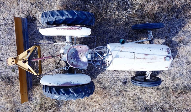
This week, I’m talking about electrical system work on my tractor. If you have no idea what I’m working on, I’ve got a 1939 Ford 9N tractor that I bought needing a good bit of work, and this series of 4 posts is documenting the repair process.

Last winter, I knew the electrical system was in rough shape. The generator didn’t work, the battery was pretty bad, and the one of the plug wires ends was rusted through and worked by being wedged in place by the spark plug so it could arc to the plug. On top of that, there’s some general wisdom about old Ford N series tractors that applies - the ignition switch is probably shot and high resistance, and the connections need some love. So, this week, I talk about fixing all that stuff. Read on for the details!
Replacing the Spark Plug Wires
Almost all the Ford N series tractors use a 6V point and coil based ignition system with a pretty standard distributor (except early 2Ns that were on magnetos). For those unfamiliar, this means that there’s an ignition coil (it consists of a few turns of primary coil and a few ten thousand turns of secondary coil to step voltage up), a set of points (contacts that allow current to flow through the primary windings and then interrupt it at the right point to trigger the magnetic field collapse and subsequent high voltage spike in the secondary windings that is enough to cause a spark in the spark plugs), and a distributor that routes this high voltage pulse to the correct spark plug. It’s a simple system, and while you can replace the points with an electronic ignition system, points are simple, fairly easy to adjust once you’ve messed with them a bit, cheap to replace, and quite reliable.
From the distributor, a set of 4 spark plug wires routes the high voltage spike to the corresponding spark plug. Or, in my case, not all of the spark plugs. The #1 plug wire (forward-most cylinder)’s wire was quite broken. I have no idea how long it’s been broken, but I do know that “wedge it in place near the top of the spark plug” was the solution used for many years. It works great, until the wire jiggles free and a cylinder stops firing. Not exactly fun to track down in the middle of a heavy snow storm.
I have no idea how old the plug wires are, and with the one obviously broken and the rest not in much better shape, a new set of plug wires was the first order of business.

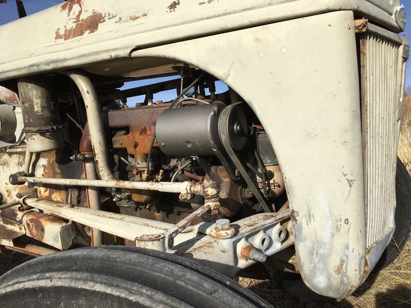
There’s a nice metal tube along the engine that carries all the electrical wires that go between the front of the engine and the back. This includes four spark plug wires, power to the points and ignition coil, and the charging line from the generator. Those of you with some EE background may be cringing at this point about the ignition wires running parallel to the charging wires and such - and your cringing is entirely correct. But I’ll touch on that later. For now, it’s sufficient to notice that the plug wires come out of the tube at each cylinder, and they come out the front of the tube by the distributor.

Below the front of the tube lives the distributor. Conveniently, this has the cylinder numbers marked on it for each plug wire! The #1 cylinder is at the front, the #4 cylinder is at the back, and, yes, the firing order is 1-2-4-3. Reinstall the wires based on the correct label and you’ll be golden.

If you’ve replaced plug wires before, you may be curious about how the whole process works, since the openings in the tube clearly aren’t large enough to fit a spark plug boot or a distributor end boot. You’re correct - you can’t fit the whole assembled wire through that tube. The plug wires come with the plug end boot installed, but the distributor end boot loose and rattling around in a bag. You have to install them yourself after running the wire.
The N series tractors don’t like modern resistor core wire. Or resistor spark plugs. They’re designed for metal core wire and non-resistor plugs. Yes, this means that you generate some comically excessive RF interference locally (also related to the issues mentioned above). That’s what the tractor is built for, and unless you have some reason to change it, leave it stock.
Removing wires is pretty simple: Cut the distributor end and pull the wire through the tube. Installing new wires is the reverse - shove them through the tube. However, this isn’t likely to work easily beyond the first wire or two. If you can’t get the wires through, spray them down with some silicone lube and try again. Enough silicone lube will solve your problem and the plug wires will slide through.
Do one plug wire at a time to make sure you wire them properly. You can remove all the wires at once, but run the new ones through one at a time. I suggest starting with #4 so you don’t have as much to fight with on the last wire or two.
A spark plug wire tool will make your life a lot easier at this point, since they’re designed to strip and crimp plug wires. If you don’t have one, well, get creative. Or go find the oldest guy in your local auto parts store and ask him for one. The younger guys are rather unlikely to know what you’re talking about.
Once the wire is through and cut to length (when in doubt, cut it long), strip a quarter inch or so of insulation from the end. Again, this is metal core plug wire. Don’t use this on a modern car. It’ll scramble the electronics with EMI and your radio will turn into an audio tachometer. But for an old tractor, it’s about right.

Before you crimp the ends on, you need to put the distributor end cap over the wire! You can’t (easily) fit it over the crimped on connection. Silicone spray lube helps here as well. Just have a bottle of it laying around for replacing plug wires and use it when you need something to slide that won’t.
Once that end is over, fold the wire core over the edge, put the end on (over the wire), and crimp it in place using the spiked bit of the plug wire tool. It should look something more or less like this when you’re done.

To get the depth set properly for the boots, coat the wire end in a good dielectric spark plug grease, shove it into the proper distributor port, and then slide the boot forward until it seats against the case. That should get everything aligned properly, and after a few weeks, the wire and boot should be nicely sealed together and not move relative to each other.

When you’re done with all that, do it a few more times. You should have four brand new plug wires all nicely routed to the distributor through the electrical tube! In addition to having brand new plug wires, the new wires have proper boots on the plug side as well. With the old wires, the tractor refused to start when wet, and I’m certain that wet spark plugs shorting out the current path weren’t helping. This should keep things nice and sealed up. Of course, make sure you put spark plug grease on these ends as well to keep corrosion away.

Replacing the Starter Leads
Unlike modern vehicles, I’ve got a 6V positive ground system on this tractor. It works if it’s in good shape, but it’s less tolerant of bad connections in the system (everything is twice the amperage of a 12V system, which means twice the voltage drop over a bad connection, and there’s less voltage to start with). The starter is the only high current draw on the tractor, but it draws an awful lot of current (well over 100A, especially with a cold motor). The more resistance in the system, the less power makes it to the starter to spin the motor.
The system installed works, but not particularly well. After taking a look at the positive ground lead, I think I see a few problems here. The battery terminal isn’t in good shape, the wire isn’t in good shape, and the connection to the frame isn’t in good shape.

The entire high amperage system is super simple. There’s a (positive) ground from the battery to the chassis. There’s a battery cable (negative) going to a big switch. And there’s a cable going from the switch to the big starter motor. All of it’s visible here, and while it works, some of it’s rough around the edges. The battery terminals, in particular, need to be replaced, and the connections are all somewhat corroded.

Instead of a starter relay like most newer vehicles have, the starter switch here is mechanical and actuates with a solid clunk. It also serves as a terminal block for the generator wire, post-cutout.

Building new cables isn’t hard if you have a bunch of 0/1 gauge wire laying around and a few copper ends. My wire is from my office battery pack, and I had some terminal ends laying around as well. They’re handy things to have. I also have a massive DC crimper that lets me put enough force on the terminals to properly crimp them. It takes a lot of force, and I can provide it!

The terminal ends just bolt on. You’ll notice the fancy red heat shrink on the left side - I found some large heat shrink locally, and other than only being available in red, it’s a good adhesive lined heat shrink that should help keep the connections in good shape for many years.
I did opt to go with the red and black painted battery terminals (and red and black cable) to try and reduce confusion down the road. Reading the positive/negative marker on a battery after years is tough, and I’d rather someone be really, really clear which end is positive if they do have to hook up a charger.

A bit of sanding to clean up the rust, a new washer, and I’ve got a positive ground connected!

The starter side connection took a few extra washers, because the terminal threads are rather mashed in the center. Stack a few extra washers on, and I can thread the nut onto the top threads, which are still in good shape. This is how it was when I took the old connection off, so I’m just repeating the assembly with new parts.

The new wiring job, all finished! I’m not a fan of the red heat shrink on the negative wires, so I may replace that at some point in the future. But, hopefully, it’s clear enough how the wiring is hooked up.

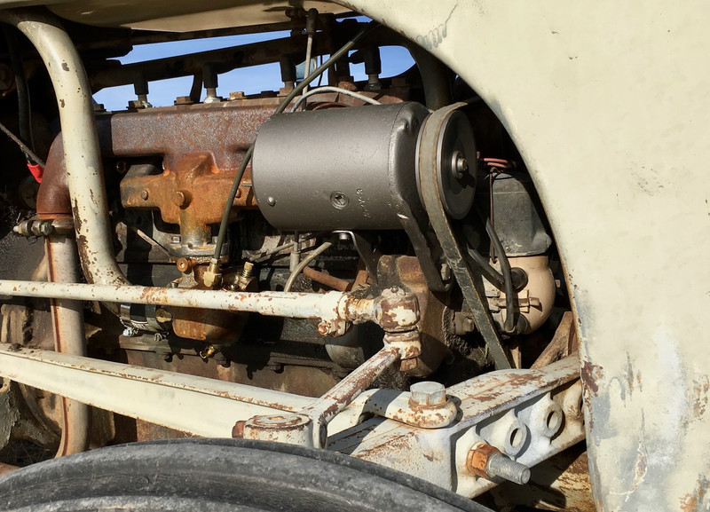
The Generator
After some work at the local generator rebuild shop (actually, about $300, between the generator rebuild, new pulley, and a new battery), I’ve got a nicely rebuilt and painted generator. The old pulley was the wrong size (and wrong threads - it didn’t actually fit and was held on by a set screw), so I have a proper unit now. They also had to repair some internal stuff (the guy was really busy when I picked it up so I couldn’t ask exactly what), and it got cleaned and painted. They tested the cutout, and the battery I brought in was quite old and didn’t hold a good charge, so I got a new one of those as well. They cleaned up the cutout relay too.
What, exactly, is a cutout relay? The original way to run a generator based charging system! A generator is really just a DC electric motor, running in reverse. The current (and voltage) output is proportional to RPM, and if you were to connect a generator to a battery, it would spin (quite aggressively - there’s a lot of mass in there, and doing this without the generator firmly clamped somehow is a really, really bad idea). The cutout is a mechanical diode. It allows the generator to charge the battery when the generator side voltage is above the battery voltage, and it disconnects the generator when the generator terminal is below battery voltage. This is a rough regulation system, but it works tolerably enough. It also means that if you keep the engine at low RPM for long periods of time, the generator won’t charge the battery at all. You have to bring the revs up to get any charging at all (though you can adjust this with the third brush adjuster).

The back of the generator contains the charge connection (the silver terminal with a few nuts on it), two bolts for holding the whole contraption together, a high/low charge adjustment screw (this should be set to high with lights or for short/infrequent use, or low for sustained high RPM running - you can adjust it to any point you want to balance out charging behavior), and another threaded screw that I have no idea about. There’s also a spring loaded oil cover on top of the bearing - drip oil down here on occasion. The dipstick works nicely to do this.

Unfortunately, my generator showed up from the shop rather misaligned. The mounting bolt wasn’t going to go through at all. It turns out that an alignment pin was long gone. The solution here is simple enough - slightly loosen the two bolts that hold the whole thing together, twist the front housing until everything aligns, and tighten the bolts down again. Not a big deal, once you understand how it’s held together.
With that resolved, the generator simply bolts back on - one bolt, tighten it down, route the belt, and you’re good to go!

Reinstalling the Cutout
The wires to the cutout weren’t in great shape either, but at this point I was getting pretty sick of pulling wires and was running out of weekend - again. I’ll replace the remaining wires next year, but for now, I just put better ends on these wires.

These are some random spade terminals I have in one of the wall mount organizers in my office. They’re close enough to what I need.

Which side goes where? Well, if you’ve got the original cutout, there should be a “BAT” side that indicates which side goes to the battery. The other side, obviously, goes to the generator. There are several different styles of cutout used on the Ford N tractors, and some of the later ones have a proper voltage regulator, so not all of them will look like this.
It’s worth noting that if your cutout seems to not work after many years of not having a working generator attached, whacking it with the handle of a screwdriver is a good first step. Mine took a good thwack to function, and now works perfectly well!

Terminal Block, Ammeter, and Ignition Key
On the back of the dashboard, there’s another mess of wires connected to the terminal block. This contains the rest of the electrical system - the ignition switch, the ammeter, and a few wire junctions.
The system is super simple. The key controls power to the ignition coil. The resistor drops the battery voltage down a bit for the ignition coil. And the ammeter shows charge or discharge (if it’s wired properly - otherwise it’ll show the reverse, like mine does right now).

My tractor has this bonus switch installed - this is a bypass for the ignition switch, because for some number of years, the keys were missing. It’s not a hard system to hotwire…

Beyond cleaning up the connections as much as I could (again, not rewiring the whole thing right now), I replaced the ignition switch. These are known to get old and have a rather high resistance, and mine is no exception. Removing the switch is easy - there’s just a nut on the back that spins off.

With the nut off, pull the whole cylinder out. Installation is the reverse of removal (tip: put the nut over the wires before you hook the wires up to the terminal block).

How bad was mine? I took the old and new switch to my office and did some testing. The best resistance I could get out of the old switch was 2.8Ω - and that took a lot of fiddling to accomplish.

The new switch? 0.2Ω. Only an order of magnitude better. The high resistance here means that the ignition coil isn’t receiving the full intended voltage, which impacts spark strength (and that, in turn, impacts cold weather starting).

I cleaned up all the terminals with some emery paper and put things back together. I’ll redo the rest of this next year when I have a bit more time (and I might even get the ammeter working in the proper direction).

Back Together
That’s about it for the electrical system! With the battery back in (and all of the rest of the work I’m talking about next week), everything works as hoped for. It starts, runs, and charges. Once I worked out that the excessive load displaying on the ammeter was actually proper charging, even the ammeter makes sense!

My color coded wiring and terminals make it easy to connect the battery charger in the proper direction. Hopefully nobody tries to charge it backwards in the future!

Electromagnetic Interference
I mentioned something about the interference on the charging system earlier. It’s bad. It’s so bad that my portable digital multimeter refuses to work on this tractor when it’s running. It simply goes into a reboot loop when connected, occasionally shows garbage, and is entirely useless. I’ve never seen this before, but there is an entry in the common tips about these tractors:
47. A digital multi-meter is a handy and usually inexpensive tool to have around the shop. But, most inexpensive digital multi-meters do not like the electrical “noise” produced by the N’s generator brushes. The test leads act as antennas and the meter gives some erratic readings as a result. Stick with the old analog meter for your old N.
Personally, I think it’s less the generator and more the plug wires running parallel to the charging connections - but I’m not actually willing to risk one of my good scopes to find out. Maybe I’ll put the old analog scope on at some point…
Next week, I’ll be talking about the fuel/oil/air system on this tractor - which is definitely something older than what you might be used to seeing!
Other Posts in This Series
1939 Ford 9N Repair Work: History and Teardown
1939 Ford 9N Repair Work: Electrical (this post)
1939 Ford 9N Repair Work: Fuel, Air, and Oil
Ford N Series Sediment Bowls (suck): Sealing a 9N/2N/8N Fuel System
Comments
Comments are handled on my Discourse forum - you'll need to create an account there to post comments.If you've found this post useful, insightful, or informative, why not support me on Ko-fi? And if you'd like to be notified of new posts (I post every two weeks), you can follow my blog via email! Of course, if you like RSS, I support that too.

