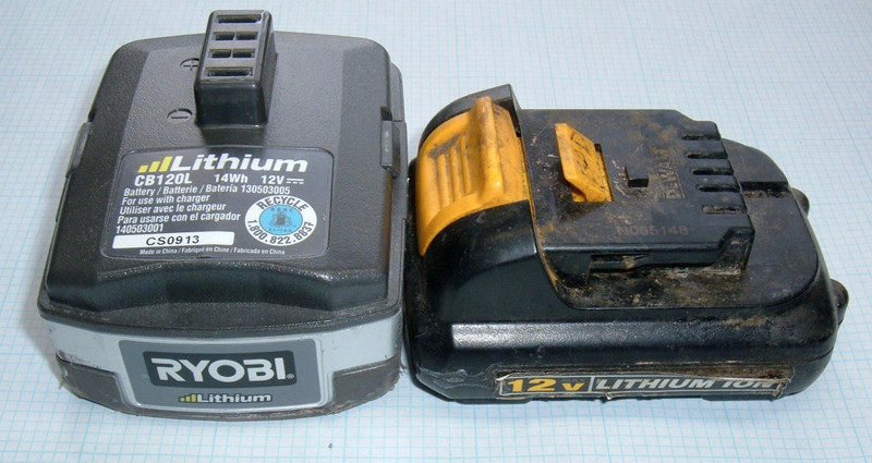

It’s been over a year since I’ve posted any tool battery teardowns, and it shouldn’t surprise anyone terribly much that I’m the sort of person who collects tool batteries wherever I roam. This week, I’ve got a pair of cute little 12V lithium batteries to pull apart - one DeWalt, and one Ryobi.

By my standards, both of these are really, really cute. I like my “100Wh” DeWalt 20V Max/6Ah battery a lot, and these are about 15Wh. Tiny. But, they are tool batteries, and I do like tearing tool batteries down - so, join me!
The DeWalt 12V Lithium Ion DCB120
DeWalt DCB120 Battery Pack (about $25 on eBay for a genuine one) is a “Type 1” battery pack (the 20V Max packs are Type 2), rated for 12V (Max), and 15.6Wh. I’ve messed with enough DeWalt packs to know that their capacity ratings are determined by someone in marketing with a calculator and not any of the engineers. If you divide 15.6 by 12, you get a neat and tidy 1.3 - so I’d guess the cells in here are 1300mAh cells, and three of them. Now, if I were to call this pack something, I’d call it something like 11.1V, 14.4Wh, but that’s me. I will never manage to get myself hired as a tool battery marketing type.
The bottom of the pack has the usual warnings about reading the instruction manual, which probably would say things like, “Do not disassemble this pack.” Not having an instruction manual, obviously, I don’t know any better than to just whip out my Torx T-10 drivers and go right in. I mean, they’re not even security bits!

Before I dive in, let’s inspect the top. This pack has the same general connection layout as the bigger lithium packs - two double height pins on the end, and six sockets in the middle. Annoyingly, these aren’t labeled like they are on the newer packs. I did a bit of probing around with the pack assembled and couldn’t make any sense of what I saw, though. Unless DeWalt has done something very, very weird with this pack, it’s quite stone dead. It’s lost in the reflection here, but someone did write “Bad” in faded marker on the latch. So, probably dead. Also of note, on the right side, you can see a 2010 build date under the muck. Probably week 34, if it’s a normal build date encoding, so late August. Almost exactly 8 years ago to this post, which long predates this blog’s existence.

Diving into DeWalt
A couple T10 Torx head screws laster, and I’m in. And… wow. Yuck. I’ve seen some nasty packs, but this is up there. Gross. It’s quite corroded, either from a vented cell or from being quite wet.
Given what looks (and feels) like an old pine needle in the top left, I’m going to guess this pack got quite wet from being left outside a long while. And/or fully immersed at some point. But, seriously, don’t leave your tool packs out in the rain. They won’t run very long afterwards, and then someone like me will make snarky comments about you in a decade.
You can see the interconnect leading straight to the end terminal on this side. The other side is the same. Like the 20V Max packs, the end terminals are double height (which makes sense, as they’re the main current carrying terminals), and they’re always live. If you were to “stick a conductive object” in the end pins, you’d find pack voltage, and it’s up to you to monitor the pack voltage and keep it from deeply discharging. I’d recommend running this pack no lower than 9V. You’ll be a hair above 12V fully charged (around 12.3-12.6V depending on where the charger quits), have useful power down to 9V, and below that, you’re just abusing the battery for no actual energy extraction. But, definitely hobbyist friendly!

The other side is more of the same. Seriously, yuck. I tried to probe the pins and sort out what’s going on with the six center pins, but with a dead battery pack, that’s tricky, and I’ll get to it later.

The DeWalt Mystery Cells
Like most of the DeWalt packs, the cells just pull out (with a tiny bit of prying if they’ve been corroded in place), leaving the bottom of the case. Given how much dirtier one of the cell housings is, it’s possible that a cell vented, but the pack was filthy on the outside, and it still could be a lot of water damage. I just don’t know what happened here, exactly.

Yuck, yuck, yuck. Corrosion everywhere. Nasty cells and interconnects.

I normally try to guess if a pack is hand spot welded or machine assembled, but this one is too gross to do much analysis on. I’ll wager hand done, though, because it’s a 2010 pack, and I’ve not seen any machine assembled ones of that age. Also, the soldering is clearly hand done, so it’s probably hand built. Talk about a boring job… wait, I build batteries!

The backside of the connector board is just a few passive components. I saw a tiny transistor on the front side, but wasn’t able to get a good shot of it. At some point, I might buzz out the boards and see what exactly they have going on, but not today.

Mystery Cells
With no clue as to what these cells are in the pack, I keep going and separate them from the case and interface board. Still no clue.

Even after removing the shrink wrap, I still don’t know what the cells are. There’s nothing useful on them, and searching for the sequences on them online returns nothing remotely resembling a battery. Unfortunately, all I can say is that these are in the 1200-1400mAh range, and some variety of lithium. Not very useful, but that’s all I’ve got.

Decoding the Pinout
With the cells out of the way, I can get around to working out the pinout on the interface.
Looking at the pins head on, the far left pair is B+, and the far right pair is B-. This is the same as the newer packs, which means if you have something sized for the 20V Max packs, and find yourself needing less voltage, and less capacity, the interface will work more or less the same.

After a bit of probing around on this corroded mess of an interface, I figured out a few more things. C1, the voltage after the first cell, is definitely the top pin, second from the right. C2, the voltage after the second cell, is the lower pin there. And, of course, if you want the voltage of all three cells, just use the B+ connection on the far left.
The ID pins appear to be both roughly 110Ω to B-. And the TH pin seems to be a 10kΩ NTC thermistor connected to B- as well. I’m not sure about the remaining pin. I’d say it’s not connected, but I do get some connections to some pins through it. On the other hand, I also get about 20MΩ between pins that shouldn’t be connected at all with the pack disassembled like this, so I’m not sure how much of that is intended and how much is the corrosion leaking.
If you find out any more details, please, let me know in the comments!

That’s about it for the DeWalt. It’s just the baby relative of the 20V Max stuff I’ve worked with before. No BMS onboard, just cells, a case, and an interface board to bring various voltages, temperatures, and ID resistance values out. And, in this case, quite the mess.

The Ryobi 12V Lithium Ion CB120L
Please be as much cleaner on the inside as it is on the outside…
The Ryobi 12V battery (about $45 on eBay, for reasons we’ll see soon) is much the same as the DeWalt, at least as far as specs go. It’s 14Wh instead of 15.6Wh, but that’s just as likely to be due to differences in creative math as to be actual capacity differences.

The bottom is the usual warnings, which I’ll probably ignore. Though I do intend to avoid lighting the battery on fire.

Unlike the DeWalt 12V battery, the Ryobi labels the negative and positive terminals. Unlike the newer DeWalt batteries, the rest of them are a mystery, at least from the outside. I did a bit of probing from the outside, but it’s sometimes easier to figure it out from the inside. The main power connectors here are a single hunk of metal instead of the dual finger DeWalt style. I’ve no idea which is better in theory, though in actual use I doubt it matters at all (especially for lower power packs like these).

However, out of curiosity, I did probe the end ports - and, hey! Voltage! This works out to 4.02V/cell, which is nicely charged. I can do some testing on this pack!

Diving In
A set of T8 Torx screws gets you inside the Ryobi. Take out the four corners, pull the top off, and… well, that’s a bit more substantial. And extremely familiar looking. Last time I got into a Ryobi pack, I saw a BMS board that looked nearly identical to the board in a Rigid pack - and this board looks pretty close to both of those. On the right, you can see the manufacturer silkscreen - Wan Nien. Apparently they also make Craftsman batteries, if you’re keeping track at home. There are labels on the board by the connections, which is super convenient, but I’ll dig into the board a bit more later.

A bit more pulling and the battery pack comes out of the bottom, with that same weird blue foam I’ve seen in the other packs. The design language of companies is always interesting to me - DeWalt doesn’t use the blue foam and rubber shapes at the bottom, and their pack is simpler than this particular manufacturer (also, I believe DeWalt builds their own packs, while clearly other companies are just rebadging packs).

Who makes the LS IMR-18650BB cells? What do we know about them? I’d guess they’re made in China. IMR signifies lithium manganese oxide cells (LiMn2O4). This is a good “power” chemistry - it trades off energy storage (mAh) for output amps. In general, you can pick where you want to sit between them, but something like a super high energy capacity cell (3400mAh) will sag badly and generally not like you pulling 30A off it. A power cell may only store 1500mAh, but will do 25-30A all day long and not care. Yes, that’s an awful lot out of a little battery. Yes, modern power cells can do it.

Pack Testing
Before going any further, I had a question I needed the answer to: Does this pack need any sort of “key” to turn it on? Some packs will leak voltage to the terminals, but won’t let you pull any power without some sort of secret code (pulling some pin to ground, or putting a resistor across two pins).
If I were some random YouTuber, I’d probably just short the pins and see what happened. But that’s not really science. There are no numbers to that process. Also, I really, really try to avoid shorting battery packs. Fortunately, I have a good load bank. Hook things up, and, yup. Just a hair over 12V on the pins.

Turn the bank on, and I pull a nice clean 2A from the pack. But… woah. That voltage drop. I’d expect a sag to 11.5V or so on 2A, not down in the 10s. On the plus side, I’ve answered my question: The pack will happily provide current if you shove wires in the terminals.

Will it do 4A? Yes, but… also, seriously, ouch. That’s a nearly 3V drop on only 4A. My connections aren’t amazing, but they’re not that bad.

Out comes my “Tool Battery Internal Resistance Tester.” This is a ZB206+ tester, wired up for poking the ends of tool battery cells. I have a few of these laying around in various configurations, and this one stays wired up like this because it’s useful, often enough. Full four wire interface, so I have accurate sag information, and it’s accurate enough for comparisons.
A sag of 2.84V on 4A implies a total system resistance of 710mΩ, which is super high for something like this. But, testing with my handy gizmo gave me per-cell internal resistance measurements in the 150-180mΩ range, which is incredibly high. You should see 30-50mΩ for a cell like this. That high measurement means the cells are old and worn out - probably both. Without an original spec sheet, I don’t know what they were supposed to be, but not this high. This pack has lived out it’s useful life and should be recycled (or re-celled, since it’s got enough smarts in it to be more than just a case for cells).

I thought about being done here, since the pack still worked, but then I looked at the voltage sag. It’s not a useful pack, and I don’t own any Ryobi tools anyway. Why not keep going? I thought I saw some cool stuff on the bottom of the circuit board.

The BMS Board
The battery management board on this pack is pretty similar looking to the one I tore down last year, but I may as well pull it off and poke around.
The main integrated circuit on this board is a S8254AA chip. It’s a standard little battery management IC that handles shutting down the pack if the voltage is too high or too low, and it supports multiple levels of overcurrent protection (so you can start a motor, but not sustain that power for too long, while still shutting down the pack instantly if someone were to try and short it out). I didn’t test the overcurrent protection.

The other end of the board contains the business end - a F1404ZS Power MOSFET rated at a whopping 190A. This serves to disconnect the battery from the output terminals if something goes wrong, which should handle both the charging and discharging side of things.

Or… wait, is it really 190A? Maybe it’s less. Maybe it’s a lot less. Maybe the package can only handle 75A. At least this datasheet is a bit more direct about the problem. DigiKey has a great article titled, “When Datasheets Attack”, talking about this very issue. If you actually sit down and try to work out what would be required for a part to meet their “current rating” in the face of actual thermal behaviors of parts, you rapidly find yourself considering things like liquid nitrogen. Plus, at high currents, a printed circuit board is not build of superconductors, so it will help heat things up as well. There’s no way this part could handle 190A at all, and even 75A is suspect in reality. But, hey, it looks like it’ll survive 750A until the legs or internal wire bonds fuse… Be careful out there! And if it seems to good to be true, it almost certainly is.

Flipping the board over, we’ve got a little thermistor in the top left corner, a UP72 UCHIYA thermal fuse (configured for 70C), and a big diode going from the negative plane to the positive plane. My guess is that this handles reverse polarity connection - if you were to try and hook up a charger backwards, this diode would short out your charger, at least after the battery bank drained through it. It’s the type of thing that I’m sure exists for a reason, but I can’t figure out where it would reasonably be used. If you tried to force current through the pack backwards, you’d drain the pack down to the low voltage cutoff (fine), and then when the transistor closed, you’d end up dumping current through the diode. It’s a weird feature, but here it is. It shouldn’t do anything in normal operation, but if you happen to know why they have this, I’d love to hear about it!

Ryobi CB120L Pinout
Finally, the pinout you’ve all been waiting for! The board actually has the terminal names printed on it, so while they’re not on the outside case, it’s easy to work them out. B+ and B- are the end connections, obviously. C1+ and C2+ are the per-cell taps, so you’ll see about 4V and 8V on them, respectively, against B-. T1 is the temperature sensor, a 10kΩ NTC unit again. And, T2 appears to be a 7.5kΩ fixed resistor - so the ID pin for the tool to identify the pack. Enjoy!

Final Thoughts
I really like what DeWalt has done with their battery packs. They’ve moved all the smarts off the pack and into the tools, allowing them to have a pack that is literally cells in a case with a dumb interface board. It’s a great way to build a battery for tool use, because there’s nothing extra in there. The Ryobi pack is a good pack, but the BMS in there is wasteful. The tool can handle the low voltage cutoff, the charger can handle the high voltage cutoff, and the whole circuit board, in the common case, will be trashed when the pack is thrown out. Yes, it grants a tiny extra bit of safety if something goes wrong, but there’s no reason you can’t have a backup overvoltage detection system in a charger (and refuse to start charging if the voltage is too low). Most of it is just extra complexity, and extra things to go wrong. I don’t see the value in that system, unless, of course, you’re Wan Nien, convincing tool makers that they all need your battery management boards and battery packs. Not a bad spot to be, really.
But, for me? I’ll stick with my DeWalt tools. The 20V Max line is clearly their flagship line going forward, with the 20V/60V FlexVolt packs being a thing, and I’m not concerned about finding packs for a long while. They use good cells, and in some cases, it’s literally cheaper to buy packs than to buy bare cells. Volume is a good thing. Plus, since the packs are nothing but cells in a case, it won’t be hard to find aftermarket ones long term.
Posts for the next month or two may be a bit erratic. I’ve got a lot of stuff I want to get done around the property before winter hits (yes, I’m thinking 3-4 months ahead, but that comes quickly), and I may not have time some weeks to get something published. I’ll see what I can get written, though!
Comments
Comments are handled on my Discourse forum - you'll need to create an account there to post comments.If you've found this post useful, insightful, or informative, why not support me on Ko-fi? And if you'd like to be notified of new posts (I post every two weeks), you can follow my blog via email! Of course, if you like RSS, I support that too.


)