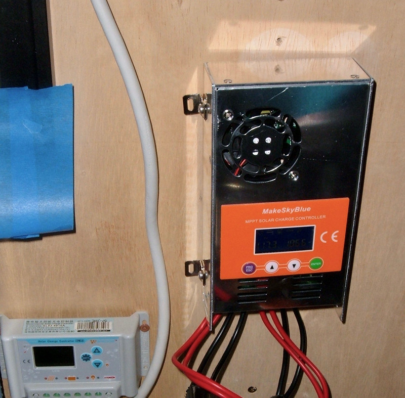

If you go looking for solar charge controllers, there’s a wide range of hardware out there, for a very wide range of price tags. My office normally runs the main array on a $600 Midnite Classic 200 - but I’ve spent some time recently running my main array on a $130 MakeSkyBlue MPPT unit.
On paper, this little Chinese unit is comparable to a Midnite Classic 200! You can get them rated for 60A output, they handle up to 190V open circuit on the solar panel side, and they’re a quarter the cost! What you can’t find are any actual reviews of the unit or details on how they function. There’s a tiny bit on YouTube, but none of the videos I’ve found dive down into the nitty-gritty of operation.

Are they any good? What do you gain or lose with this unit as opposed to one that’s 4x the cost? Well, you might be able to expect that I’m about to dive into that with my usual amount of detail - and you’d be right!
The MakeSkyBlue 60A MPPT
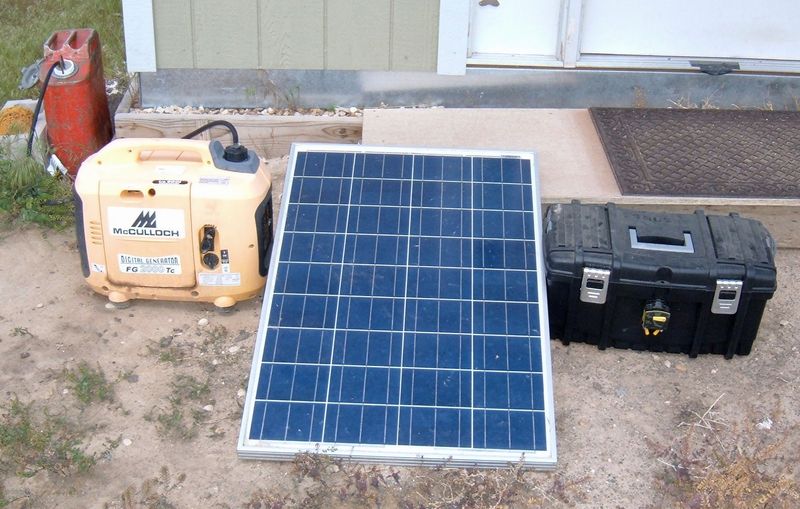
For the past 2 years, my office has run perfectly happily on the $600 Midnite Classic 200 I put into service originally. It’s a beast of a unit and does a great job of charging my batteries. But, when it had to go in for service (some inductor whine that was getting really, really annoying), I considered my options for running in the summer and decided that I’d try out a cheaper unit for a while to see how it works in actual service. These are promising units on eBay, are rated for up to 190V on the PV side, and you can get them in a range of output currents. I’ve got a 60A rated unit, because… well, mostly because a 30A unit wasn’t going to cover my needs, and I don’t trust Chinese units past about half their rating. Since I need a bit over 30A, getting a 60A unit seemed reasonable to me.

The spec sheet looks pretty good, too! These units can handle 12V, 24V, 36V, and 48V battery packs, this particular one is rated for 60A output current (2800W on a 48V system, which is comfortably above the 2280W of panel I hung on it), custom voltages for absorb and float, and a handy little 5A rated output (most sales pages claim you can’t hang more than 100W on it, but the actual manual says you can put 5A on it) with timer control. It supports up to 190V open circut on the solar side, which is quite high for a unit this cheap. Plus, you can set it up for lithium!
It doesn’t have quite the guts of the Midnite Classic (79A output and a lot more configuration), but it’s less than a quarter the cost - and, importantly, there’s that 190V rating. Four panels in series (which is what I have) will have an open circuit voltage of 160-170V, going up in the winter. Mine typically stay below 150V in the summer, but only barely, and I want the headroom.
The connections on the bottom are smaller than I’d prefer, but for both the panel hookup (PV) and the battery, the units have two terminals for each. They’ll take an 8 gauge wire, and you might be able to get 6 gauge in, but that’s really pushing it. There’s plenty of wire size for even 60A output for long periods. If you’ve got the connections tight, that is. I ran 30A through it regularly on 10 gauge wire and had no trouble at all with anything getting even the slightest bit warm.

Before I cover installation and configuration, let’s take a detailed look inside. I did actually open this up before I installed it, to convince myself that it wouldn’t blow up my battery bank and office. I’ve got good breakers on both the panels and the battery, but, still. What does a $150 Chinese MPPT unit look like on the inside?
MPPT vs PWM
MPPT: Maximum Power Point Tracking. I go into a bit more detail about MPPT in a post from a few weeks ago, but what matters this week is that a MPPT charge controller is fundamentally a variable buck (or, occasionally, boost) converter. It takes a higher voltage from a set of solar panels and transforms the energy to a lower voltage, higher amperage battery charge current. It also, ideally, seeks out the maximum power point of a particular array (you could say it “tracks” the “maximum power point,” if you wanted), but the key is that it’s a power converter - not just a switch. The most common way of doing buck or boost conversions is with inductors, capacitors, a switch, and a diode.
A PWM charge controller, while far cheaper, doesn’t do power conversion. It simply connects the panels to the battery if the battery voltage is too low, and disconnects them (or rapidly connects and disconnects them) when the voltage rises up. You can build a PWM controller with just a cheap switching power transistor and a microcontroller, but you need something more for MPPT.
Going Inside
To get into the unit, there are 6 screws around the top. Remove all six, pry the lid off, and you’re in!
The first thing you probably notice, in the lower right corner, is a set of inductors and capacitors. This is a really, really good sign for something that claims to be a MPPT unit - and makes me believe that it actually is going to do the power conversion. A pair of electrolytic filter capacitors at either end are there to smooth the power out (they’re quite beefy units), and then there are some control electronics and a few transformers in the center, with a few connections for the controls on the lid. Nothing too exotic so far, but definitely not just a rebadged PWM unit.

Two of the connectors are keyed so you can’t put them in backwards, but the last connector (the thin ribbon cable) isn’t. The exposed metal tabs face up or the keyboard won’t work right. But, if you look closely, there’s a seven pin connector in the lower right! Does this have anything interesting on it? Serial, perhaps? A communication interface?

Some rapid analysis with a continuity tester indicated that the far left pin was ground (common to battery negative). I powered the unit up with my bench power supply, grabbed my handy little DSO138 oscilloscope, a jumper wire, and probed for anything interesting. Sadly, all I found was that the center pin matches the toggling red LED that indicates the processor is alive. You could use this as a liveness check, if you wanted. The other pins are connected, but don’t offer anything that looks like a serial datastream off them. They’re probably JTAG-ish, and with the right interface, you might be able to debug the unit, but reverse engineering a Chinese charge controller blind is a bit more effort than I really feel like putting in at this point. I’ve got compost bins to build, trailers to upgrade, and lawns to create!

Removing the Board
Removing the board from the case is pretty simple: Remove all the screws. The screws are actually well placed - they run through the switching transistors and help keep them pressed to the back of the case as a heatsink. Good design, here! With the board out of the case, there’s nothing new to see, but it does make it easier to take photos of certain sections.

The unit is rated for a maximum PV input voltage of 190V - and here’s a 200V rated capacitor on the input side. Excellent! Assuming, of course, the capacitor is legit - but I’ll assume it is. This isn’t a dirt cheap unit that would be using fake components. It’s rare to see Chinese systems derated slightly from the absolute max they could briefly maintain, but here it is. At least some derating!

On the logic side of the unit, there’s a Texas Instruments TMS320F2802x Piccolo Microcontroller - or, at least, something that claims to be one. I haven’t found any evidence online of these being counterfeited, but that doesn’t mean much. It’s a 60MHz capable 32-bit microcontroller with some analog-digital converters (voltmeters) and some high resolution, high frequency PWM (pulse width modulated) outputs that are perfect for driving things like buck converters. It’s always interesting to see what chip is used to control various devices, but this chip looks very well suited to being the brains of a MPPT unit like this.
I can’t decide if the top of this board is hand soldered or poorly machine soldered. I’d originally assumed that it was machine soldered on the top, but looking at it closer, there’s a good chance it’s hand soldered. Things like the “103” chips in the lower left being flipped relative to each other, and the uneven solder blob size on the surface mount components makes me wonder. It’s fairly consistent, but look at that blob on the brown component in the lower right. There’s a lot of flux residue on the board as well, and the microcontroller pins really look hand soldered to me (they remind me very much of the surface mount rework I’ve done). If I had to bet, though, I’d say it was hand soldered, or at the very least, hand reworked after a machine went through.

In the other corner of the board is a set of 3 identical inductors with paired capacitors. This is the main power conversion side of the board. The inductors and capacitors, plus some switching transistors and diodes on the other side, make up a set of buck converters. By rapidly switching how the circuit is configured (something, say, a high frequency PWM output is perfect for), these can convert a high voltage input into a lower voltage, higher current output (exactly what we want here).

Each inductor is paired with a capacitor, as should be expected for a buck converter. These are 105J400V capacitors - or 1uF, 400V polyester film capacitors. The 105 means 1uF, J means 5% tolerance, and 400V means, well, 400V. Polyester film capacitors are generally longer lived than the normal electrolytic capacitors, though a good bit larger for an equivalent capacitance. They make up for it with longer life and great ripple tolerance. Plus, they don’t dry out like electrolytic capacitors tend to do. I probably won’t have to replace these capacitors like I have with some electrolytic ones on an old mainboard.

The Backside of the Board
Which, I promise, doesn’t go as well with Wizard of Oz as it sounds like it should.
Flipping the board over, there are some current traces and a bunch of semiconductors. If you’re playing along at home, the top side has the inductors and capacitors, which means the bottom side must have the switching transistors and diodes. Presumably, three pairs! And I see six large ICs opposite the inductors! The pads on the bottom of the semiconductors are insulators that keep the (electrically active) metal back from grounding out on the case - I removed one of them to show off the metal back (and some of the others stuck to the case anyway).

For the switching transistor, we’ve got a HY1920 N channel MOSFET. I can’t find much except a single foreign language reference for it, which tells me it’s N channel and rated for 90A of current and a maximum voltage across it of 200V. Again, 200V part, 190V rated board… I’m surprised to see the conservative ratings, but they continue through the whole product. I’m also quite surprised to see a 90A part used when a 30A part would work, but perhaps someone got a good deal on these. I wouldn’t be at all surprised to find different components if I were to purchase another unit in a year.

Finally, we have a STTH3003CW - a rather old secondary rectifier (diode), rated for 300V (!) and 30A (15A per leg). Again, very conservative, but given that the datasheet I found dates from 1999, I expect someone found a box of these laying around. Or, given the fact that this particular one seems to be quite beat up, got them from someone who removed them from other devices.
I even verified they’re using both legs. It’s in no way a given for something like this that parts are used properly, but this seems to be done properly. The combined 30A of rectifying capacity is comfortably more than the 20A each section needs to handle, so, quite conservative here as well!

There’s no question that the back side of the board is hand soldered. Check out those solder globs! It’s not a bad way to link things together that have to deal with a lot of current, but it’s definitely not machine built.
Why might you design a system like this? The easy answer is that the same unit is sold from 10A to 60A capacities. Since each “chunk” can handle at least 20A (if not a bit more), you can simply populate the number of regions needed. I’d bet good money the 10A version of this charge controller only has a single inductor/capacitor/transistor/diode pair filled in!

Temperature Sensing
Finally, on the back, there’s a little thermistor. This is a standard device for determining temperature, and just about every bit of electronics has one. The red piece of heat shrink over it helps prevent it from grounding out against the case over time, and the black chunk of foam presses it against the case back.
Since all the switching gear (transistors and diodes) use the back of the case as a heatsink, this is a very reasonable place to put the thermistor. Notice above that if you were to only populate one bank, this would still be in a good spot to monitor temperatures.

In case there’s any doubt, the front of the board has the “NTC1” label for where this thing solders in. NTC - Negative Temperature Coefficient. A thermistor!

This is a perfectly reasonable place to put a temperature sensor if you want to derate the output based on temperature, but it’s a perfectly silly place to put a sensor if you want to measure battery temperature. Supposedly this unit has battery temperature compensation, but I can’t see how it would, given that the only temperature it can measure is the hot section.
Front Plate and Cooling Fan
The front plate has a custom LCD display, and four buttons. Plus a cooling fan.

Flipping it over, there’s a display unit that has some variety of potted little IC to drive the display (the black circle in the center - it’s an epoxy type coating over a bare integrated circuit), and a ribbon cable coming off the top with five conductors. Given that there are four buttons and one needs a ground (or voltage source) to easily detect button presses, I can bet that one of the five conductors is common, and the rest are tied to each button.
Because the entire display module is glued in place, I can’t easily go deeper here. I do want this unit functional when I’m done with it!

The cooling fan is a thin 60mm unit, should you need to replace it. I’d assume it’s 12V, but you might pull it off and check before replacing it, if needed. The fan doesn’t run that often, even under a heavy load, so it’s likely to last a long while.
It is a tiny bit silly that the fan sucks air across the front of the circuit board when the heat generating parts are on the back and use the case as a heatsink, but in operation it seems to work just fine, and the fan isn’t running excessively (at least with my 30-35A loads), so I wouldn’t worry about it. Using the whole case as a heatsink is a really good idea, though one might want to avoid mounting it firmly against a wall. Leaving a bit of an air gap will help the unit cool.

Installation
Installation in place of the Midnite Classic required a bit of work, because the Classic has large screw terminals that take up to 4 gauge wire, and the MakeSkyBlue doesn’t. It has pairs of smaller terminals, so I built myself some adapters. I’m not going to say you should do something like this, because you probably shouldn’t, but they work just fine and I built them out of stuff I had laying around. A few ring terminals, some wire, and you’ve got adapters!
To interface with the larger wires coming off my solar array and battery bank, I bought some screw on ring terminals for the bigger cables (from eBay, where else?). They’re cheap enough for something like this. Small bolts do a great job of connecting ring terminals together.
With the unit on the wall, I powered it on (batteries first, as always for charge controllers), and proceeded to configure it before adding solar power to the mix.
Configuration
You can find the manual here, if your unit didn’t come with one, and it’s readable enough. Before using things, you need to set the absorb voltage, float voltage, and battery type (lithium or lead acid), plus optionally the output hours.
One thing to be aware of: All the configuration is done in “12V units.” The controller will automatically determine the system configuration (12V, 24V, 36V, 48V) based on battery voltage on power-on, and it uses this to multiply the set voltages before actually using them. So, if you set 14V on a 48V system, you’re actually setting 56V. It’s not a very intuitive system, and I quite firmly dislike it.
With the unit powered on, press the PRG/ESC key, and you’ll enter the configuration menus. The up and down arrow move you through the settings, and the Enter button will select one for you to change - at which point the up/down arrows change it, as might be expected in a reasonable interface.
There are five menu options that set various things - D00 through D04. After you’ve set options, power cycle the unit. Otherwise it may not actually use the new values.
D00: Output On Time
D00 allows you to set the output time - how long the output terminals are on. I didn’t actually use this feature, so I’m not quite sure what it’s referenced to. Morning or the start of solar production, perhaps. If you figure it out, let me know in the comments! The range here is 0-24 (hours).

D01: Float Voltage, in 12V Form
As I mentioned above, everything on this charge controller is referenced to 12V battery ranges. This is the first of the options where this appears. If you have a 12V system, everything works as expected, and you can set the float voltage from 11.0V to 16.0V directly. If you have a higher voltage system, this is multiplied by your system scaling factor (2-4) to get the desired voltage. It’s not that annoying to deal with, but I don’t understand why they’ve done this unless they’re reusing some old firmware. It also means that the lowest increment of voltage on a 48V pack (like my system) is 0.4V - which is an awful large jump in voltage.

D02: Absorb Voltage, in 12V Form
Same as above, but for the absorb voltage. I’ll touch on the charging algorithm a bit more below, but that 0.4V spread is really annoying here. My bank of 8x Trojan T105RE batteries specifies a charging voltage of 59.28V, temperature compensated. My options here are 58.8V (14.7 x 4), 59.2V (14.8 x 4), and 59.6V (14.9 x 4). Yes, flooded lead acid should be charged that high in off grid use. But I can’t really dial it in that precisely. Does it actually matter? Probably not, but the controller reports the actual battery voltage properly, so it would have been nice if someone updated the firmware to let you specify things properly. You can set the voltage in the range of 12.2V to 17V.

D03: Output Cutoff Voltage, in 12V Form
If you’re using the output feature on this controller (the OU terminals), this sets the low voltage cutoff from 9.0V to 12.5V. Below this battery voltage, the output won’t turn on at all. It’s useful if you’re using the output terminals, otherwise you can safely ignore this too.

D04: Is Lithium?
If you have a lithium battery (or something else that doesn’t need separate absorb and float voltages), set this to 01. Then, the float voltage never happens, and the unit only charges to (and maintains) the absorb voltage set in D02. You should use this if you’ve got something that’s not lead acid.
Now, have you power cycled the unit? Good! Add solar.
Running Displays
The normal status displays can also be cycled through with the up/down arrow keys.
PV Status
The PV status screen shows the state of the incoming solar - voltage and total watts. It indicates the battery capacity (more or less), and shows if the charge is active, and if the output is active.

Battery Status
The next screen over shows the battery state. This shows you the actual battery voltage, as well as the charging amps (if you have PV attached and are charging). This isn’t showing in “12V Units” - I just have the controller attached to a bench power supply here, and it’s not charging anything.

Status and Temperature
Next up is the general status and temperature display. The left number is the system state, and the right number is the temperature in Celsius.
Valid modes, by number, that make roughly no sense at all:
- 3.0: Night mode. Not charging.
- 4.0: MPPT mode (extracting the maximum power from the panels, also known as “bulk charging” - the battery is below the absorb voltage and the system is cramming current in).
- 7.0: Absorb mode. The battery has risen to the absorb voltage and the controller is attempting to hold it there.
- 8.0: Float mode. The battery has finished the absorb charge and is being held at the float voltage.

Errors/Protection Mode
Finally, the last display is the error/fault display. Again, the numbers make no sense at all, but:
- 18: Input PV Voltage Too Low (such as not being connected).
- 60: Over-temperature Protection. Will clear when the unit cools down.
- 63: Battery Overvoltage.
- 65: Battery Undervoltage.
- 71: Input PV Voltage Too High.
- 73: Charging Overcurrent.
I don’t quite know why 73 could happen, because a MPPT charge controller is in charge of the current and can limit the power to prevent it, but it’s in the manual.

Operating Notes: How Does It Work?
Finally, after all that - the part you have (hopefully) been waiting for: Operating notes! I used this controller in my shed for just about 2 weeks while my Midnite Classic was in for inductor replacement, so I had a chance to use it in a real world situation.
Of importance here: I have multiple charging systems (the other solar one is a pair of east facing panels hooked up to a PWM controller, though I also have a generator I could use), and I don’t use the puny little output on something like this. My inverter has a fat pair of 2/0 wires going to the battery bank, and regularly pulls 30A in operation if everything is powered on. That 5A output isn’t going to run much!
First things first: This gizmo does work. It (more, sometimes radically less) tracks the maximum power point acceptably and charges the battery bank. However, it doesn’t work well, it really doesn’t work well in my setup, and I wouldn’t use it outside a very limited set of circumstances except as a backup.
MPPT, RPPT, Whatever…
Maximum power point tracking? Why not random power point tracking?
I know my power system pretty well. I’m in there quite a lot, and I do tend to pay attention to how things are operating. On most days, I have a lot of logging (The Blackbox Project, a Raspberry Pi 3, and my Midnite Classic serve to handle this - this is one reason I upgraded my Raspberry Pi with a SSD), so I can see how the system runs, and I know that the Classic does solid power point tracking.
The MakeSkyBlue? Well, it tracks the maximum power point acceptably, except when it decides to go chasing buttercups in the field, well and completely off the rails (much like Tootle). Quite a few times during the two weeks I had this thing running, I’d look over and see that it was running my panels below 90V during the middle of the day. At one point, it was nearly down to 60V. This is quite at odds with what I know about my panels, which is that they operate (in any decent illumination, which this was) between 110 and 120V. Operating at 63V? That’s… not right. Not even close to right.

And the controller knew it! I went outside, toggled the panel breakers off and back on, and the exact same charge controller, without being rebooted, found a much more reasonable operating point of 116.5V. Does this sort of thing make a difference? Absolutely! When it found a random power point, it was producing 318W. After power cycling, the same exact set of panels was producing 761W. That means it had found a “Maximum Power Point” of 42% of the actual maximum. Not acceptable.
It did it more than once. Another time, it decided that it should operate the panels at 74.5V, pulling a whopping 806W out of them. Cycle the breakers, it went back to a more reasonable 123.7V and 1314W. That’s only about 62% of maximum. Same conditions, same battery, same panels, just toggling the breakers. I got tired of logging it and would just go toggle the breakers if I saw it running below 100V, and it would reliably get a lot more power out. So, no clue what’s going on there, but it’s pretty well annoying.
Charging Algorithm: First We Float, Then We Absorb
If you’re not familiar with lead acid battery charging terms, I’ll refer you to my post on lead acid battery maintenance. But, in a nutshell, charging lead acid is pretty simple. You shove current in until you hit the absorb (higher) voltage, you hold it there for a while until the batteries are fully charged (which can be calculated by specific gravity, charging current, or, if you must, time). This is a well understood process, and most charge controllers will do something reasonable.
This one might - if it’s the only charge controller in the system. But, in my system, it’s most decidedly not, and it’s very definitely the second charge controller to come online, because my two east facing panels outproduce my 8 south facing panels for the first hour or two of the day.
As near as I can tell, this controller will use the absorb setpoint early in the day, and looks for the charge current to taper off to some moderately low value before switching to float. If the current is low enough (and I don’t know exactly what the value is), you switch to float. This is reasonable enough. The problem is that it doesn’t actually know the charge current - only what is going out the terminals. And with other charging systems, you can impact that, quite substantially.
What happened in my setup is that, in the morning, the morning panels would start bringing the system voltage up. They can actually get the bank up to absorb voltage by themselves if the batteries start not particularly drained and it’s a cool, sunny morning. The MakeSkyBlue detected this rise above the float voltage, decided that the batteries were full, and happily settled into try and maintain the float voltage.
And then I’d show up and turn computers on. At this point, generally, there was enough sun to maintain the float voltage, so the system hung out at float voltage, charging, but not charging particularly quickly.
At some point, I’d draw enough power (or a cloud would go over, or the controller would seek to a random power point and stop charging sufficiently) that the battery bank voltage would drop down below float for long enough. At this point, the MakeSkyBlue decided that it needed to switch to the absorb setpoint, and would then seek the absorb voltage. However, because I always draw a good bit of power in my office, especially on sunny days, it would never see the drop in current that would trigger float, and would just stay in absorb the rest of the day. This is good for charging the batteries, but staying in absorb for 8-10 hours is really hard on the batteries, and is absolutely not needed (my batteries only need 2-3 hours of float this time of year). I could trip it back into float if I tried by unloading the controller and pushing the voltage up, but it’s just not a useful way to operate.
I’d care a lot less if this were a small, 10-20A rated 12V controller that was likely the only controller in the whole system, but for a 60A rated controller with a 5A output? There’s no way that the controller will be regulating the output side of a system that can charge at 60A and 48V!
Most of the sellers talk about how you can pair these units together (and sell “120A” units that are just two of the 60A units), but with this sort of charge behavior? No. There’s a reason good charge controllers will sync between themselves regarding the current charge mode (bulk, absorb, float) - and it’s to avoid the sort of silliness I saw with this unit with only a very small extra controller operating. Don’t pair these units if you care about your battery bank.
If you only draw loads off the output terminals, I assume the controller will monitor that and do something reasonable about the charging behavior, though I really don’t know what. I don’t have the equipment to simulate that sort of setup without having parts of my main system offline, and I don’t have the funds to set up a separate charging lab to really dial in on things like this.
So: What’s the Difference?
With all that said, what’s the difference between a $150 MakeSkyBlue charge controller and a $600 Midnite Classic? Mostly, that I was truly excited to get the MakeSkyBlue off my wall and replace it with a proper charge controller once again. The Midnite Classic may not be that far ahead in terms of absolute raw numbers, but it makes up for it in design and battery awareness. The Midnite Classic:
- Monitors battery temperature directly, with a probe that sticks on the battery bank, and does temperature based charge compensation properly.
- Can monitor (with the WhizBang Junior shunt) the battery charge current and do the proper thing regarding charging, regardless of how many other loads are on the system. It will happily drop into float while I’m pulling 20A, if the charge current has dropped low enough.
- Reliably seeks the actual maximum power point. I’ve never seen the Classic do something silly like operate my array at 60V during the middle of the day.
- Has good reporting, good data logging, and is accessible over Modbus, Serial, and can coordinate multiple units together.
So, you know, other than being a good charge controller versus sort of working, most of the time, no difference at all! And, it is better than nothing.

I wouldn’t recommend the MakeSkyBlue for anything but a small system that could run off the output port - but, even then, I’m not sure I’d use this controller. The inability to reliably seek the maximum power point defeats the entire purpose of this unit, and you’d be far better served by a proper panel array and a competent PWM controller for that sort of setup. PWM isn’t evil, by any means. It isn’t quite as efficient as a MPPT unit in the winter, but it works just fine, and if you match the panels and batteries, it’s going to work a lot better than a fancier unit that occasionally seeks off into the wild blue yonder.
What could you use one for? Something like I used: A backup charge controller that’s nominally compatible with a Midnite Classic 200, or any other 4S panel arrangement. If you do that, I’d suggest forgetting about the separate absorb/float settings and just using one voltage, somewhere in the middle, and trying to get a nice charge controller back online in a hurry. It works, in a pinch, but if I ran this year round, I’d murder my battery bank in short order.
Design Thoughts, Limitations, and Lithium Hazards
If I had to guess, I’d say that this is an evolution of an old, lower power, 12V only MPPT controller. The menu options being only in terms of 12V systems support this, as does the somewhat weird charging algorithm that assumes all solar and all loads are going through one unit. It’s a very reasonable way to design something like a 10-15A 12V charge controller (with 5A of output to run lighting or remote radios or something), but it’s a very silly way to design a 48V/60A capable unit (that, per my analysis, is actually capable of somewhat more if you were to ask).
Another major problem I have is that the voltage settings don’t let you support any lithium pack you want, as the sales pages tend to imply. You can only support a certain range of voltages, because the voltages supported are a multiple of the 12V system. If you’re using the “lithium” mode where all you have are absorb voltages (12.2V-17V), you can support packs in the 12.2V-17V range, the 24.4V-34V range, and the 36.6V-68V range (the 36V and 48V ranges overlap). But, you’d better make sure the voltage is in the correct range on startup, or the controller will do something bad. What sort of bad?
The multiplier is set by the voltage at power-on:
- 9-15V: 12V (1x multiplier)
- 18-29V: 24V (2x multiplier)
- 30-39V: 36V (3x multipler)
- 40-60V: 48V (4x multipler)
Let’s say you’ve got a 10S lithium pack - 30V empty, 42V fully charged (or perhaps a bit higher, if you’re using new cells and feel the need to stress them). You hook it up after building it at 36V (a pretty standard shipping charge), configure everything for the 3x range (14.0V absorb voltage, which works out to 42V with the 3x multiplier). All is well, but at some point you are messing with your system and have to power cycle the charge controller - with a fully charged battery. Now, with about 42V on the terminals, it detects the system as a 48V pack, configures a 4x multiplier, and proceeds to try and charge the pack to the configured 14V setting - but now, it tries to push 56V into your pack. That’s 5.6V/cell, which is well into the “exciting and likely on fire” realm I desperately try to avoid. Whoopsie!
A proper charge controller (say, a $600 Midnite Classic) solves this by simply letting you set the voltages, and storing them in absolute terms. There’s no hidden multiplier involved. I tell it to charge a lithium pack to 42V, and unless I completely factory reset the unit, it stores the settings and will charge to 42V. Period.
So, the overlap between the automatic voltage detection and the set voltages means that you probably shouldn’t use this pack with a lithium battery. It claims to support it, but unless you’re really careful, there are some hidden gotchas that can get you into serious trouble. If the unit allowed you to select the multiplier, and latched that with the voltage settings instead of trying to be “smart,” it would be a lot safer to use. Or they could have just done the work to let you pick a voltage in the supported output voltage range instead of trying to be smart about it. Auto-detecting on first startup is great, auto-detecting on subsequent startups is absolutely hazardous with lithium.
Final Thoughts
I really wanted to like this controller. Based on the spec sheet, it looked like a really good backup controller for my Midnite Classic - if something goes wrong, I can bolt this in and go on my way. To some level, this is true - this controller is substantially better than nothing, and I do plan to keep it around as a backup (unless someone sends me a nicer controller to mess with as a backup). But, for daily use in a system like mine (or any system of decent size)? No. If you have any significant loads, it’s going to keep your batteries in absorb all day - unless you have multiple charging sources, then it might just keep them in float all day. Until the evening, when it ramps them up. The behavior is just too unpredictable to rely on.
Plus, the RPPT anti-feature where it won’t run the array properly is genuinely irritating. Not everyone has easily accessible breakers for their solar array (mine are outside, so require a brief walk, but not climbing onto an RV roof or something), and it doesn’t seem to correct that quickly. I tried to see if it would seek in the right direction, and it refused to self-correct. Not useful.
So, if you absolutely need one of the cheapest MPPT units out there for some particular use case, and you can deal with all the quirks of this unit, buy one, I suppose. But it’s likely to be penny wise and pound foolish. There’s just no good reason to use one of these units for any system you care about.
Unless you have 4 panels in series. Most of the other cheap MPPT units I’ve seen that handle a 48V pack are limited to about 150V on the panel string, and won’t tolerate something like 160-170Voc (as my string is). If you’ve used three panels in series, awesome. Four? Well… you might just have to tolerate this unit as a backup, because, again, it’s better than nothing, and it’s the only cheap unit that will support that high a voltage.
If you find reviews like this helpful, I’d appreciate if you toss a few coins in the tip jar over on the right (the “Donate” link at the bottom of the right sidebar). I try to review things that I find useful and actually need, but if there’s a demand for more reviews of solar charge controllers, I’d be happy to mess around with them. They’re just a bit on the expensive side for me to buy for fun, though. I’m also happy to get a loan of a unit for a few weeks to mess around with, if you happen to be selling something that would work with my system and want an independent review of it!
Happy Solaring!
Comments
Comments are handled on my Discourse forum - you'll need to create an account there to post comments.If you've found this post useful, insightful, or informative, why not support me on Ko-fi? And if you'd like to be notified of new posts (I post every two weeks), you can follow my blog via email! Of course, if you like RSS, I support that too.


